At first glance, these effects don't seem related. Some move fluids, others distort space, and others reveal or hide parts of an image. But they all rely on the same underlying mechanism.
When you write a shader, your graphics card runs the fragment() function once for every pixel it draws. For instance, all the pixels of a Sprite2DSprite2D node.
The graphics card processes each pixel independently, entirely in parallel. But if pixels have no awareness of each other, how can you, as a shader artist, create a program in which pixels cooperate to form an image? How does a shader communicate a pixel's position and how can Godot use a texture inside of a shader?
The answer to these questions is UV coordinates.
Why is it called the 'fragment' function?
In graphics programming, a fragment is a pixel the graphics card is considering drawing on the screen.
The term comes from the GPU's rendering pipeline, where geometry gets 'fragmented' into individual screen pixels for further processing.
In Godot, fragment() is the function you write to decide the final color of each candidate pixel.
In practice, fragments and pixels are similar enough that they're used interchangeably.
In this guide, you'll learn:
What UVs are
How to visualize a pixel's position using color
What texture sampling is and how it relies on UVs
How to use UVs to create movement
What are UVs?
You can write a very simple shader to change the resulting color of a fragment:
shader_type canvas_item;voidfragment(){
COLOR =vec4(1.0,0.0,0.0,1.0);}
Each shader needs a type
Every Godot shader starts with a shader_type declaration that tells the GPU what
kind of node the shader runs on.
canvas_item covers all 2D nodes, like Sprite2DSprite2D and ControlControl.
Other types include: spatial for 3D objects, particles for particle systems, sky for sky rendering and fog for volumetric fog effects.
In this guide, all shaders use canvas_item.
How do I write shaders in Godot?
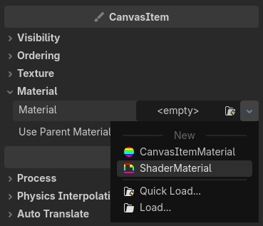
You can assign a shader to a CanvasItem's Material. The material property is found under Inspector > CanvasItem > Material.
To create one, click on the dropdown and select ShaderMaterial.
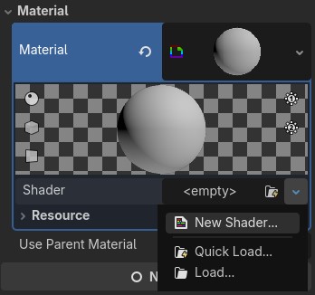
Next, click the shader dropdown to assign a 'New Shader...' to the material.
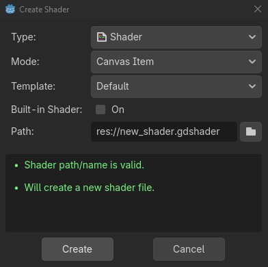
Finally, for a 2D text-based shader, set the type to 'Shader', the mode to 'Canvas Item' and click Create.
This works, but every pixel produces the same color.
To do anything interesting, pixels need to know where they are.
The fragment() function relies on built-in variables which hold information about the current pixel.
One of the most important variables is the UV, which tells each pixel where it is.
UV is a vec2 and it holds the position of the current pixel as a pair of normalized coordinates, both between 0.0 and 1.0.
Why normalized? Why not just pixel positions?
Normalized coordinates mean the shader produces the same result regardless of the node's
size. A pixel at UV(0.3, 0.6) is always 30% across and 60% along, whether the sprite is 32x32 or 1024x1024.
What is a vec2?
In shaders you will often have to work with numbers that relate to each other.
Instead of separately keeping track of them, you can group together two numbers with vec2, three numbers with vec3 and four numbers with vec4 variables.
The vector's components can be accessed by accessing their x, y,, z and w properties in order, depending on how many components each has.Alternatively, you can achieve the same goal by accessing the r, g, b and a components. These are just aliases and are generally used when accessing vectors that represent color.
Visualizing the UV
Shaders can not print values like normal scripts. The most direct way to understand what those 0.0 and 1.0 values actually represent is to visualize the UV itself.
Let's see what happens when the x and y components are placed in the red and green channels of the COLOR built-in:
voidfragment(){
COLOR =vec4(UV.x, UV.y,0.0,1.0);}
The result is a mango-colored square. Each corner reveals something about the UV:
Top-left is black: both x and y are 0.0 here
Top-right is red: x reaches 1.0, y is still 0.0
Bottom-left is green: y reaches 1.0, x is still 0.0
Bottom-right is yellow: both x and y are 1.0
This reveals how the UV space is laid out:
x increases from left to right
y increases from top to bottom
The origin (0.0, 0.0) is at the top-left corner
Most effects rely on this knowledge. For instance, the center of the UV space sits at (0.5, 0.5).
If you know the distance from each pixel to this point, you get a circle centered in the middle:
voidfragment(){vec2 center =vec2(0.5,0.5);float radius =0.2;float dist =distance(UV, center);if(dist < radius){
COLOR =vec4(1.0,0.0,0.0,1.0);}else{
COLOR =vec4(0.0);}}
Isn't using if statements inside shaders bad for performance?
The GPU processes groups of pixels in waves.
When pixels in the same wave take different branches, some have to wait while others finish.
Because of this, it's common that you'll see recommendations against using if statements.
In practice, it depends. Modern GPUs handle many cases well and do not lead to conditional branching for most common cases.
Plain if statements and conditions that check a uniform value are generally safe to use.
In cases in which real branching happens, it's still worth it if the condition skips big chunks of code.
If you want to avoid the if statement entirely, step(radius, dist) returns 0.0 below the radius threshold and 1.0 above it. Invert the step: 1.0 - step(radius, dist); to get the same result as the previous shader example.
It's more compact, but harder to read.
The distance() built-in
The distance() built-in function returns the distance between two points.
For example, distance(vec2(0.0, 0.0), vec2(0.5, 0.5)) returns the distance between the top-left corner and the center of the shader.
In the example we get the distance between all UV coordinates and the center of the canvas. When picking all points that have a distance smaller than the radius we end with the points forming the disc with the center in vec2(0.5, 0.5) and the radius 0.2.
Texture Sampling
So far, every example calculated COLOR through code alone. This process is also known as Procedural Generation.
Code is powerful, but it limits what you can draw.
Complex shapes, painted details and hand-crafted art are much easier to express in a texture than through mathematical functions.
Godot gives you the option to use such textures inside of your shaders.
A procedural shader calculates its result per pixel. It stays sharp at any resolution.
A texture has a fixed number of pixels. This means that, at a certain scale, effects using them will lose quality.
The tradeoff is precision. A texture allows you to paint exactly what you want, pixel by pixel. A procedural shader gives you infinite resolution, but constrains you to what math can describe.
In practice, most shaders combine both: textures for the art, then use code to transform them.
Godot provides two built-ins for sampling textures:
TEXTURE: a variable storing the node's texture
texture(): a function that reads a color from a given texture
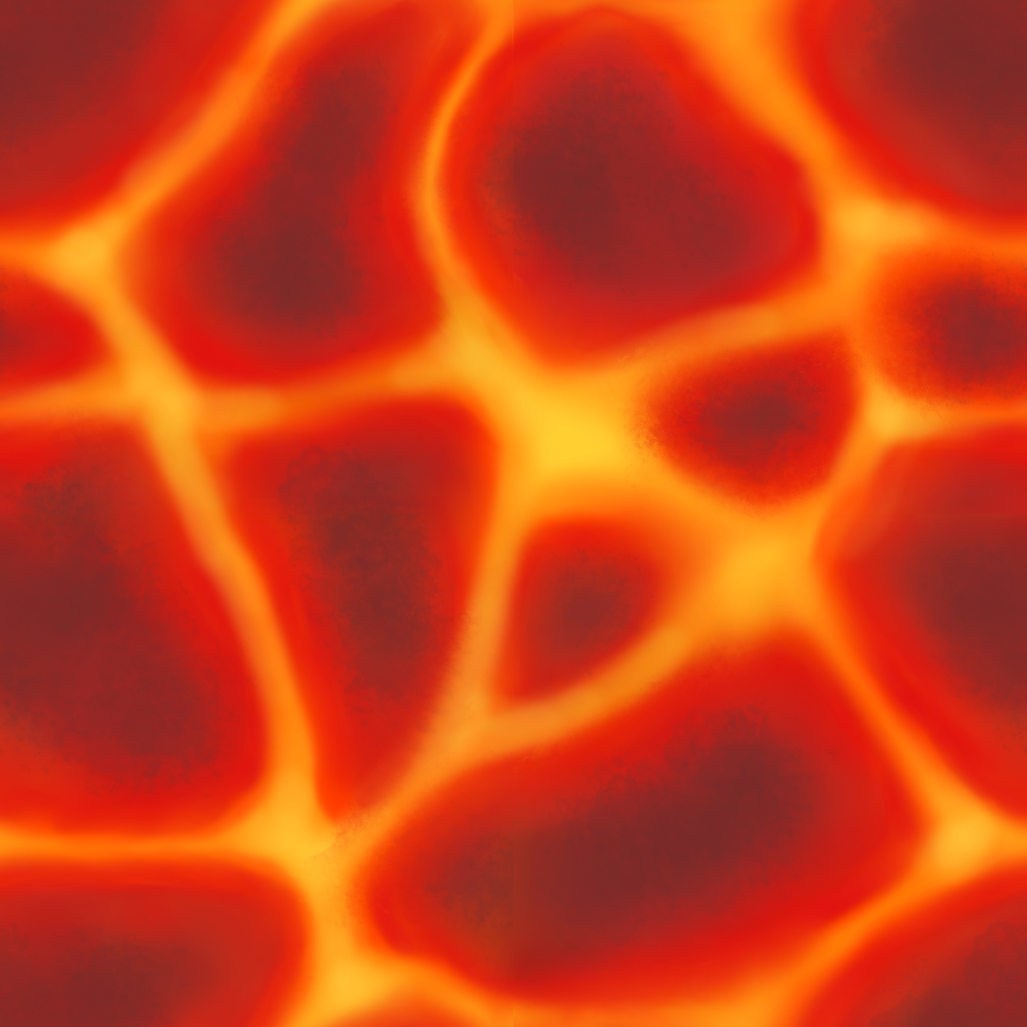
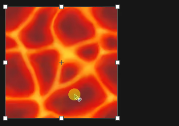
What's left to you is to decide where to sample from. That's exactly where UVs come in. Let's sample a lava texture to see it in action:
voidfragment(){
COLOR =texture(TEXTURE, UV);}
When you pass the raw coordinates, each fragment samples its corresponding texel. This is what Godot does by default for any CanvasItemCanvasItem with no shader attached.
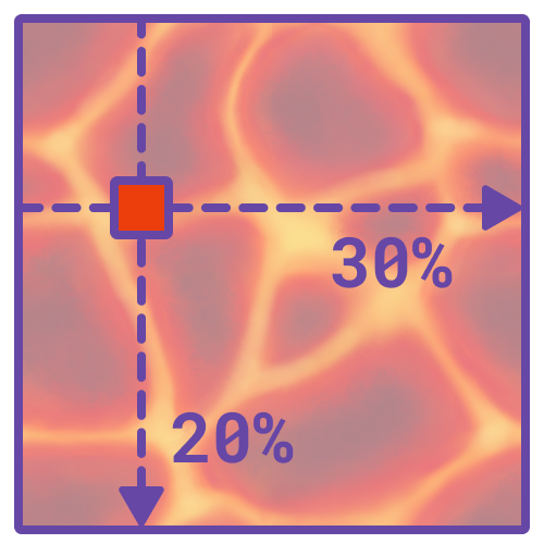
For example, a pixel sitting at (0.2, 0.3) will sample a texel color that's 20% across and 30% down the texture.
Pixel sampled at the UV coordinates (0.2, 0.3)
What happens when coordinates fall between texels?
This is especially visible in low resolution images. Texel coordinates are integer numbers.
For an image that's 64 pixels wide. 10% of that is 6.4.
In such cases, Godot needs to decide upon a color that's close enough to one at an integer coordinate.
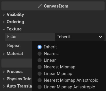
The decision is based on the sampled texture's filter mode:
Nearest: pick the color of the closest texel.
Linear: interpolate the color of surrounding pixels
You can change this property in the Inspector in the CanvasItem > Texture > Filter dropdown.
Movement
When writing shaders, a common effect you'll create is movement, making a texture appear to scroll or flow. The technique is simple: change the UV coordinates before sampling. If you do this, each pixel samples a texel at a different position than it normally would. Combine this with the TIME built-in to make the texture look like it's moving.
The TIME built-in
The TIME built-in returns the time since the engine has started, in seconds.
This means that TIME is continuously increasing. You can plug it in a mathematical function to create an animation that follows it.
Let's start with a simple example and shift the horizontal coordinates before sampling. Adding 0.5 to UV.x moves the sampling point halfway across the texture:
voidfragment(){vec2 shifted_uv =vec2(UV.x +0.5, UV.y);
COLOR =texture(TEXTURE, shifted_uv);}
Repeat Modes
No, your screen is not broken. This is actually what you expect to see when sampling outside the predefined [0.0, 1.0] region of a texture. When you add 0.5 to UV.x you shift the texture sampling point.
For example, the pixel at the coordinates (0.0, 0.0) now samples the texture at (0.5, 0.0). That's the highest point at the middle of the texture. On the other hand, a pixel located at (1.0, 0.0) samples the texture at (1.5, 0.0).
How does Godot sample a pixel that's horizontally 150% across a texture? It all depends on that texture's repeat mode.
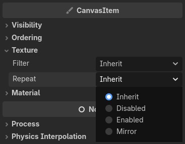
Texture repeat modes define what happens when sampling a texture outside of its [0.0, 1.0] region. The three repeat modes are:
Disabled: The texture does not repeat. Godot clamps the coordinate to the [0.0, 1.0] range. This is exactly what happened in the example. Each UV horizontal value between [1.0, 1.5] sampled the corresponding pixel at 1.0.
Enabled: The texture repeats. Godot wraps around the [0.0, 1.0] range and acts as if identical textures were tiled infinitely in all directions. For example, a pixel with the UV coordinates (1.5, 0.0) would sample the texture at (0.5, 0.0).
Mirror: The texture mirrors. This is similar to the 'enabled' mode. Imagine the same identical textures being tiled, with the exception that every other tile is flipped.
Here's how the previous shader behaves in all repeat modes:
Repeat Mode: Disabled
Repeat Mode: Enabled
Repeat Mode: Mirror
Repeat modes can be changed in the inspector under CanvasItem > Texture > Repeat.
The repeat mode for a node's texture defaults to Disabled. You can get rid of the stripes by checking if the shifted UV lands in the [0.0, 1.0] interval. If it does, you draw the pixel, otherwise you discard it:
For a scrolling texture, though, the Enabled repeat mode is usually what you want.
Discarding pixels
The 'discard' keyword tells the fragment shader to not return any color for a fragment.
It acts like an early return. No other code gets executed for that fragment.
A shader that reaches 'discard' doesn't return a transparent pixel; It doesn't draw one at all!
This is an example where the difference between 'fragment' and 'pixel' is noticeable.
You can refer to the result of this shader as a 'fragment', as it is a potential pixel, but you can not refer to it as a 'pixel' when it's discarded.
At first, it might feel weird to add0.5 to the x coordinate of the UV and see the texture move left in the shader output. If you take some UV values and check the sampling result for each of them, the result starts to make sense. However, that involves a lot of calculations and, while technically accurate, is not very intuitive.
To better understand shaders it's usually a good idea to zoom out. After an operation, instead of looking at the resulted fragment, see how it influences the shader as a whole.
For example, I like thinking of the UV as a shader's canvas. Inside an image editing program, when you move, scale or rotate the canvas, you don't do it to the actual image, you do it to the region on which the image is drawn.
The Canvas being moved 50% to the right. Just like the UVs!
OldDew
Teacher at GDQuest
Movement Animation
A static offset moves the texture to a different position. For actual animation, the offset needs to change every frame.
Replace the fixed 0.5 offset with TIME:
voidfragment(){vec2 shifted_uv =vec2(UV.x + TIME, UV.y);// Discard logic is no longer needed// As repeat mode is now set to 'Enabled'
COLOR =texture(TEXTURE, shifted_uv);}
Every frame, TIME grows larger and pushes the sampling point further right. In reality, though, lava is viscous. To slow down the animation, multiply TIME with a value smaller than 1.0.
voidfragment(){vec2 shifted_uv =vec2(UV.x + TIME *0.05, UV.y);
COLOR =texture(TEXTURE, shifted_uv);}
Scroll on both axes at once by offsetting UV.y as well:
voidfragment(){vec2 direction =vec2(1.0,0.5);vec2 shifted_uv = UV + TIME *0.05* direction;
COLOR =texture(TEXTURE, shifted_uv);}
You can change the direction vector in which lava flows by modifying its x and y components. However, a more intuitive method is defining the vector as a uniform.
Direction
uniformvec2 direction =vec2(0.0,0.0);voidfragment(){vec2 shifted_uv = UV + TIME *0.05* direction;
COLOR =texture(TEXTURE, shifted_uv);}
Uniforms
Uniforms expose shader properties to scripts or the inspector. Define them in the global scope, outside any function:
uniformvec2 direction =vec2(0.0,0.0);
Unlike regular variables, uniforms can't be written from within the shader. Still, you can dynamically update the effects of a shader at runtime. To do that, call set_shader_parameter inside a gdscript with the uniform name you want to change and the new value it should take:
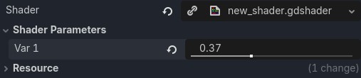
Some types accept editor hints that control how the property appears in the inspector. A hint_range on a float produces a slider:
uniformfloat var1 :hint_range(0.0,1.0)=0.0;
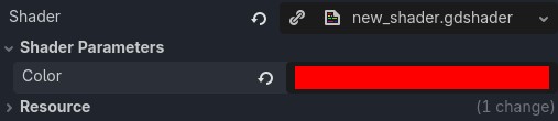
source_color on a vec4 produces a color picker:
uniformvec4 color : source_color =vec4(1.0,0.0,0.0,1.0);
The direction vector controls the direction and relative speed of the scroll, but to make the lava more believable the shader also needs an organic wobble effect.
For such an effect, both the x and y axes need a slight offset that depends on their current position. There's no hard rule for obtaining that direction. Any oscillating function like sin or cos added to the initial UV coordinates leads to a convincing fluid-like motion.
Try different values or functions to get interesting results. Here's one possible configuration:
Direction
uniformvec2 direction =vec2(1.0,0.5);voidfragment(){vec2 wobbled_uv =vec2(
UV.x +sin(UV.y *5.0+ TIME)*0.03,
UV.y +sin(UV.x *3.0+ TIME)*0.06);vec2 shifted_uv = wobbled_uv + TIME *0.05* direction;
COLOR =texture(TEXTURE, shifted_uv);}
Oscillating functions
sin() and cos() return a wave-like value that smoothly cycles between -1.0 and 1.0.
You can tweak the behavior of these waves individually by adjusting:
Frequency: How fast the wave changes. You can change it by multiplying the input of the function.
Amplitude: The overall strength of the wave. You modify it by multiplying the entire result outside the function.
Offset: The shift in the wave's position along its cycle. Add a value inside the function to move the wave. You can also add TIME, so the wave animates.
Combine these properties and you get the generic shape of the whole function:
Notice how the lava shader uses different values for the horizontal axis (5.0 frequency and 0.03 amplitude) than the vertical axis (3.0 frequency, 0.06 amplitude). This gives each axis a unique speed and wave size and creates a more organic and believable fluid motion.
Shaders are usually what separates a game that looks good from one that really stands out.
You just learned how to manipulate UVs, one of a shader artist's most reliable tools.
And it doesn't end here. This is just the first of many techniques you'll learn and combine to create stunning and expressive visual effects.
Most importantly, have fun and experiment with what you learned!
OldDew
Teacher at GDQuest
Become an Indie Gamedev with GDQuest!in GDSchool
Don't stop here. Step-by-step tutorials are fun but they only take you so far.
Try one of our proven study programs to become an independent Gamedev truly capable of realizing the games you’ve always wanted to make.