Modern game engines like Godot use many shaders under the hood.
What is a shader? It's a program that runs directly on your computer's graphics card. Shaders control how the GPU draws 3D models, particles, 2D sprites, and more to the screen.
When getting started making games, you don't necessarily have to learn how to program shaders. Godot provides you with many built-in visual effects that you can tweak without writing shader code. Also, the Godot community created many free shaders you can find on Godot Shaders, or in GDQuest's free and open source shader collection. You can copy their code into your game and use them as a starting point.
But to get the exact look you want, have fun creating unique visual effects, or make your game run faster, you eventually need to learn how to code shaders.
For example, when you see a glowing portal in a game, grass moving in the wind, or animated 2D water in a platformer, these effects are powered by shaders.
This effect will teach you many transferable techniques that you will need for all sorts of 2D and 3D visual effects:
Drawing simple shapes using math
Creating soft edges and transitions with the smoothstep() function
Using masking to combine multiple shapes into complex ones
Using periodic functions to animate the visuals over time
Using noise to create effects that look more natural
Sampling textures to read colors from any image and bring visuals into your shader
You will also learn how shaders are different from traditional programs and the mindset they require. You will learn how to think like a technical artist by breaking complex visual effects into small, manageable problems. You will also learn how to debug shaders using Godot's great shader visual debugging feature.
Pre-requisites
This guide is for people who have no experience with shaders or graphics programming. But it focuses on visual effects, so we don't teach basic programming concepts like variables or loops. We assume you already know the basics of GDScript and Godot.
You should be comfortable with:
Navigating the Godot 4 editor
Creating nodes and changing their properties
Reading and writing common GDScript code
If you are new to Godot, here are some free resources to help you learn the basics:
Learn GDScript From Zero is our interactive app to learn the basics of code with Godot's GDScript programming language
This tutorial is sponsored by all the new and experienced developers who are currently following GDQuest's curriculum to learn how to make games with Godot.
Shaders can seem scary because they require a different way of thinking than traditional programming. While gameplay code is sequential, shader code runs entirely in parallel on the graphics card.
This is a large guide, so bookmark it, work on it over several sessions, and come back to it later for a refresher! Like any form of programming, it will take time and practice for shaders to become comfortable.
Let's start with the minimum amount of theory you need to not get lost as we start coding our shader hands-on.
NOTE:
If you need help, you encounter a problem, or you have feedback to share, you can post it in the first-shader-godot-4 channel in our Discord server.
1. The vertex and fragment shaders
As I mentioned in the introduction, a shader is a program that tells your graphics card (Graphics Processing Unit or GPU for short) how to draw on the screen.
To draw on the screen, the GPU goes through a series of predefined steps called the Rendering Pipeline. These steps turn a shape and input data like images into the pixels you see on the screen. By default, the engine takes a texture image that you provide and draws it within a Sprite2DSprite2D node's bounds. You can use shaders to change the default behavior of these steps.
To get started coding shaders in Godot, you only need to know about two stages of the pipeline: the vertex shader and the fragment shader.
We will code a fragment shader in this guide
In this guide, we will code entirely in the fragment shader, which is the shader type you will use most in 2D games. But we still need to quickly look at the vertex shader because it prepares the shape that the fragment shader fills with pixels.
In short, the vertex shader controls the outer geometric shape and the fragment shader draws pixels within this shape.
The vertex shader
There's one thing to know about the graphics card: it can only draw triangles that are then filled with pixels. A Sprite2DSprite2D node, for example, is a rectangle made of two triangles. Within this rectangle, the GPU paints transparent and opaque pixels to create the sprite's appearance.
So, to draw an object to the screen, the GPU first needs to determine the shape of the object. It does this using vertices, which are the points that define that shape.
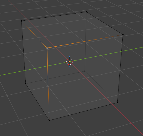
If you have ever created a 3D model, you are already familiar with vertices. They are all the corner points that you can edit when working with a 3D art program. In this image, I selected one vertex of a cube in the 3D art program Blender:
The vertex of a 3D cube
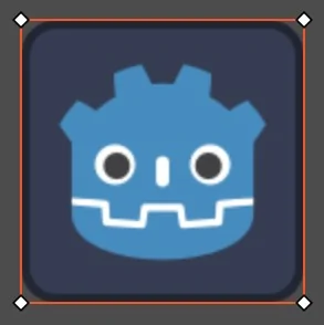
But vertices are not exclusive to 3D models. Flat 2D elements like sprites need to have a geometric shape as well. For example, in Godot, the rectangle shape of a Sprite2DSprite2D node is defined by four vertices. The four vertices are represented as diamond shapes here:
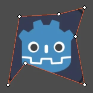
Other 2D nodes, like Polygon2DPolygon2D, can have more than four vertices to create more complex shapes:
By default, the GPU gives a node its shape by using the vertices as they are and placing them on the screen. The vertex shader lets you change the position of each vertex and, by extension, skew or offset the shape of the object itself.
In Godot, we use a function with a specific name to tell the GPU which code to run for each shader stage. To use the vertex shader, we define a function called exactly vertex() in the shader code.
When we define the vertex() function, the GPU runs it for every vertex in parallel. We won't need this function in this guide because we don't need to change the portal's outer rectangle.
We're talking about it here because it always runs before the fragment shader in the rendering pipeline. This means you will run into it every time you work with shaders.
We won't write any vertex shader code in this guide, but knowing that it exists and where it fits in the pipeline will help you understand learning resources about shaders and other people's shader code.
OldDew
Teacher at GDQuest
The fragment shader
After the vertex shader gives a node its outer shape, the rendering pipeline needs to determine the color and transparency of each pixel inside that shape. The step that controls this is the fragment shader.
By default, Godot takes the node's texture and places all of its pixels into the shape output by the vertex shader. But you can change this behavior by writing your own code in the fragment() function.
The fragment shader runs for every pixel of an object and returns the color that pixel will get. You can assign a value to COLOR inside a function named fragment() to modify or completely change the resulting image. For example, this code turns a sprite into a black rectangle:
voidfragment(){
COLOR =vec4(0.0,0.0,0.0,1.0);}
Now that you know what the fragment shader does, let's create the smallest scene on which we can test one.
In the next section, we will set up a Sprite2DSprite2D and give it a custom shader so you can try this yourself. We will build our portal from that.
Why is this called a 'fragment' shader if it runs for every pixel?
Strictly speaking, saying "the fragment shader runs for every pixel" is not exactly right, but it's a helpful lie that almost everyone uses!
In graphics programming, a fragment is a candidate pixel. Fragments don't always end up as real pixels because during the rendering process some of them might be covered by other objects or discarded altogether.
But in everyday shader work, you very rarely need to make that distinction. Thinking of a fragment as "the current pixel" lets you focus on how the shader works without getting distracted by the details of the rendering pipeline. So, unless explicitly mentioned, you can consider a "pixel" and a "fragment" as being the same thing.
2. Setting up the Godot scene
Believe it or not, you have already been using shaders ever since the moment you first opened Godot. Every game object you see in the game is drawn using a default shader that takes the object's texture and paints it on the screen.
To create your own visual effects, you replace a node's default shader.
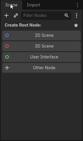
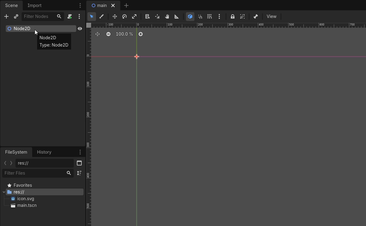
Let's set up a scene where we replace a sprite's default shader. In a new Godot project, go to SceneNew Scene and click 2D Scene in the Scene dock to create a Node2DNode2D at the root.
Then, add a Sprite2DSprite2D node as a child of the Node2DNode2D. You can click on the AddAdd button in the Scene dock to open the Create New Node dialog and search for Sprite2DSprite2D.
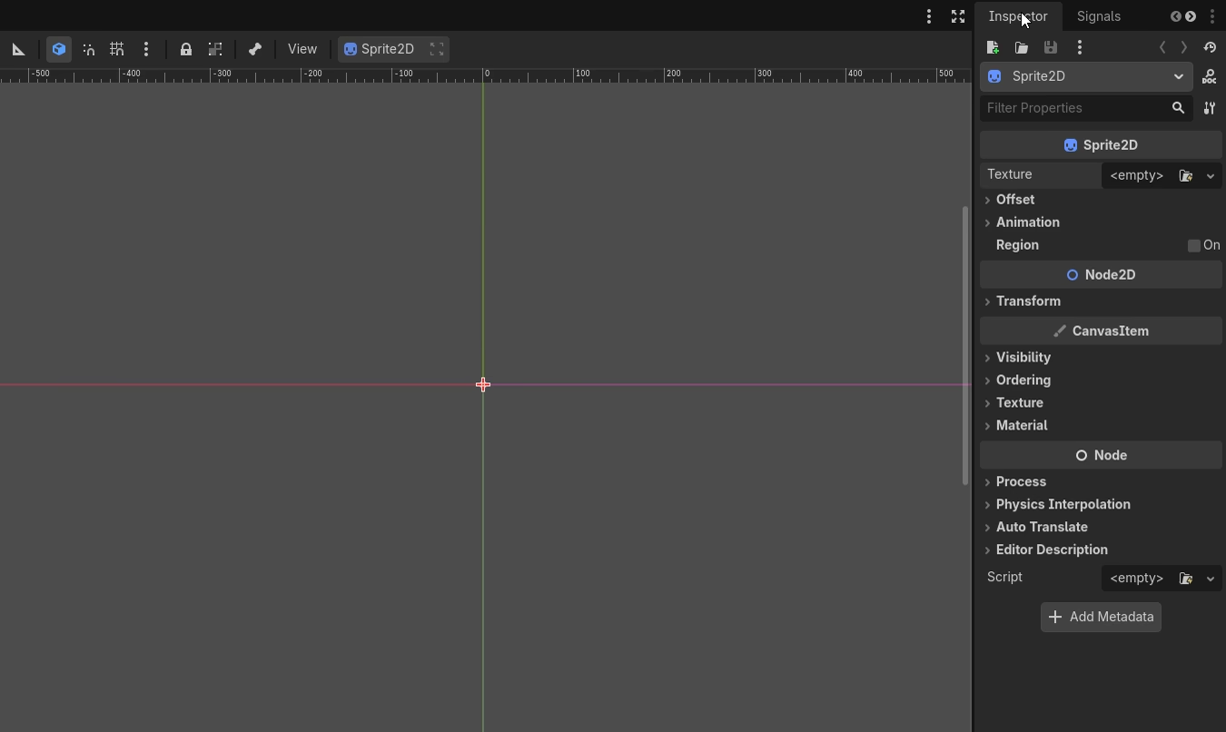
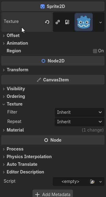
The Sprite2DSprite2D node appears in the Scene dock, but it's still not visible in the 2D game view because it currently doesn't have a texture. To give it one, go to the Inspector dock where you'll find the Texture property. Click the LoadQuickQuick Load icon to open the texture selection dialog and double-click the default Godot icon to load it.
The selected image now appears in the viewport. This is the default shader I was talking about in action! Godot draws the sprite's texture on the screen based on the Sprite2DSprite2D node's position.
Let's override this default shader.
Attaching a shader material to the sprite
To attach a custom shader to a sprite, we need to first create a material and then create and load a shader program into it. What's the difference between the two?
A shader is a chunk of reusable code, similar to a script you would write in GDScript. It defines how Godot should draw a node on the screen. You can reuse a shader across multiple scenes and materials.
A material is a specific configuration of that shader. Let's say you code a shader that can tint a sprite. You could have one material that tints the sprite green and another material that tints the sprite red. Both materials would use the same shader.
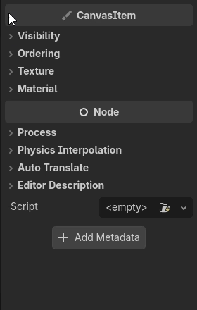
Let's add a material to the Sprite2DSprite2D node. Go to the Inspector and locate the MaterialMaterial property in the CanvasItemCanvasItem section. Click the "empty" slot and select ShaderMaterialShaderMaterial from the opened menu to create a new shader material. This creates a new ShaderMaterialShaderMaterial resource, in which you can create or load shader code.
Click the ShaderMaterialShaderMaterial resource to expand it. Then, click the "empty" slot next to Shader and select New Shader....
Creating a new Shader
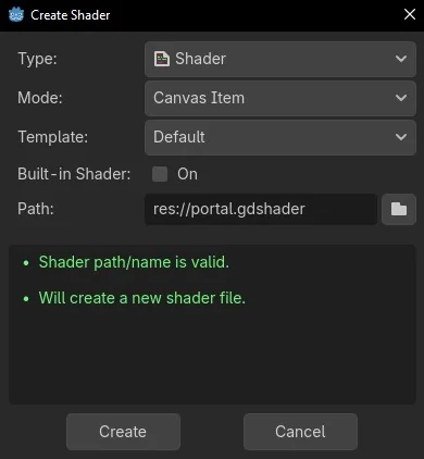
This opens the shader creation dialog. In this dialog, leave the default values as they are:
When Type is set to ShaderShader, it creates a new ShaderShader resource that allows you to type shader code. VisualShaderVisualShader is another option that uses a visual editor to design shaders.
When Mode is set to Canvas Item, it creates a shader that can be used with 2D nodes.
Change the Path to res://portal.gdshader and click Create. This will save your shader to a file.
This is what your shader configuration should look like
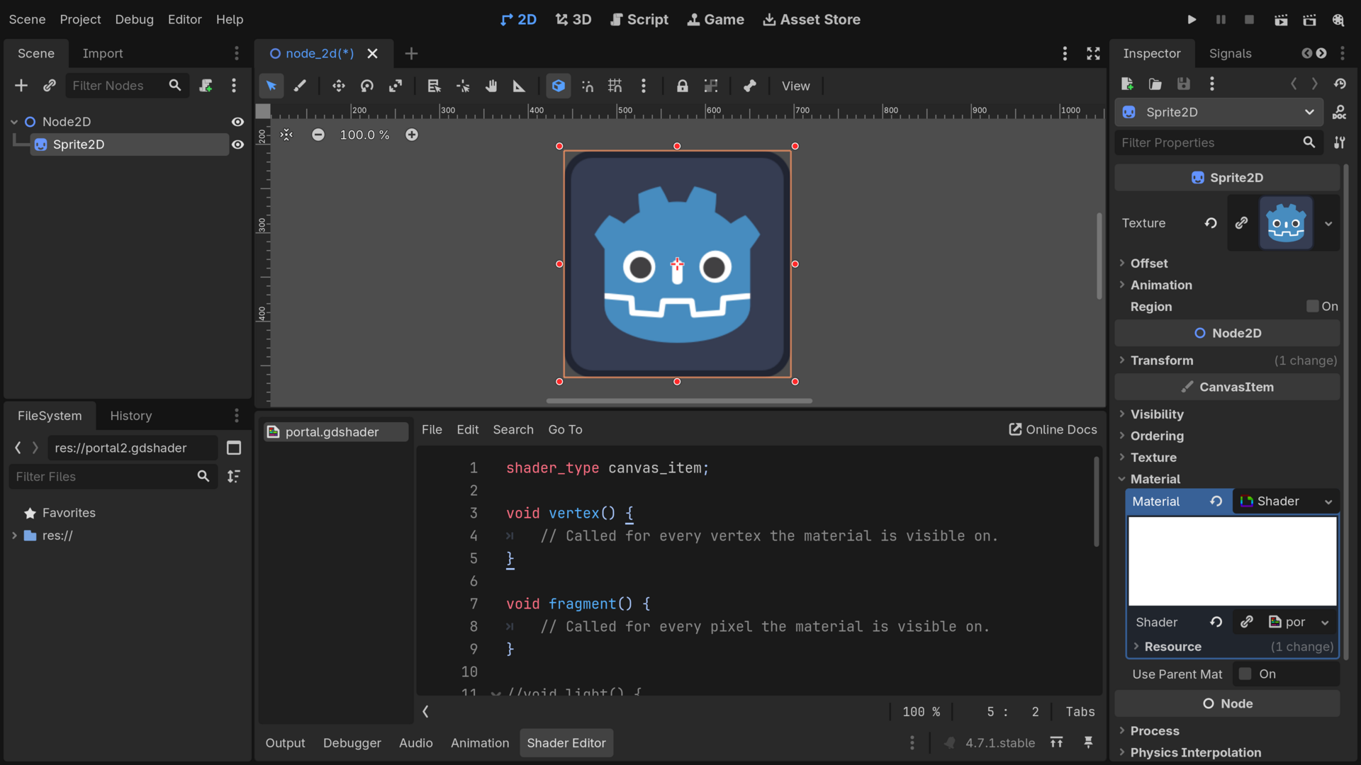
Godot opens the Shader Editor bottom panel and fills your new custom shader with the default template. You can control how it draws the sprite by editing the vertex() and fragment() functions Godot created for us. At this point your scene should look like this:
Our scene is ready to start experimenting with shader code. Before we start coding, let's talk about how we will plan the portal's implementation so you have an idea of what we will create and how you break down a complex effect into manageable parts.
3. Planning the portal's implementation
This is the portal effect we will work toward over the next sections. This is a copy running live in your browser, so feel free to tweak the parameters! These are some of the ways in which you will be able to configure the final effect in Godot:
Color Inner
Color Rim
Breathing Strength
Displacement Strength
Noise Speed
The portal effect
How do you even start making this kind of effect?
The portal has two colors, it wiggles around, and it grows and shrinks over time. It's hard to understand what's going on. How could you even write it all at once?
You don't have to!
Creating a shader is an iterative process, just like the rest of game development. Instead of trying to create an effect all at once, you build it step by step. Even professional technical artists create shaders by combining many simple effects.
OldDew
Teacher at GDQuest
At every step, you follow the same basic cycle:
Start with the smallest step towards your goal.
Find a tool that can help you complete this step in your shader programming toolkit.
Try using the tool on your shader code and see what happens.
You repeat this loop until the shader is complete.
So, where do we start? We break the portal apart into its core elements and look for an achievable goal. Let's look at the portal once again:
Look at the effect closely: what shape does it roughly look like?
A circle! This gives us a starting point: we will first draw a blue circle and then work our way from there.
How do we then animate it, deform it, or create the brighter outer ring?
Well, just like when building game systems and mechanics, you need to build a shader toolkit and gain experience to break down a complex effect into manageable steps. We're here to learn how to write shaders, so this time, I will break down the steps for us.
This is how a technical artist would approach this:
Draw a circle procedurally by measuring the distance between pixels
Use masks to split the circle into an outer ring and an inner circle
Smooth the mask edges to add anti-aliasing around the procedurally generated ring and circle shapes
Animate the shape using periodic functions and time
Use a noise texture to deform the shape and add high-frequency details
By combining these techniques one at a time, you can work your way from drawing a simple flat shape up to the animated space portal.
This is the plan we will follow. First, we will paint every pixel in the shader with one color. This will show the effect as it changes each step of the way.
OldDew
Teacher at GDQuest
4. Drawing your first pixels with shader code
Let's start with the smallest step: painting every pixel with one color. We will first make our shader work, and I'll tell you more about the syntax and how it all works afterward.
First, define a variable to store the color. Type the following line of code in the fragment() function in the Shader Editor. This is the lighter blue color you saw previously:
That's because creating a variable only stores a value. It doesn't tell the graphics card to use that value when drawing.
To tell the graphics card what to draw, you have to use the shader language's special predefined output variables. For example, to select a color, you assign the color you want to the special COLOR variable.
Add a new line of code at the end of the fragment() function to assign your color to the COLOR output variable.
voidfragment(){vec4 portal_color =vec4(0.23,0.35,0.65,1.0); COLOR = portal_color;}
Your sprite should turn completely blue like this:
The COLOR output tells Godot what color to apply to the current pixel. Since the shader runs for every pixel, the whole sprite becomes blue.
You have just coded your first shader! Before we look more closely at the color values, let's see why this small function that just sets the COLOR variable paints the entire sprite with the same color.
How the syntax of the GDShader programming language works
GDShader, Godot's shader programming language, is based on the OpenGL Shading Language (GLSL). It's a simplified version of GLSL that makes it really easy for technical artists to adapt existing shaders to Godot.
The syntax of GDShader is closer to languages like C and C++ than to GDScript. Thankfully, you can adjust by mapping what you know of GDScript to this programming language. The most important differences are the following.
GDScript uses indentation to determine where a function or a block of code starts and ends. In GDShader, you use curly braces ({}) instead. The opening curly brace starts the function or code block, and the closing curly brace ends it:
voidfragment(){// This is the fragment shader function body.}
Also, like in most languages with curly braces, every line of code in a code block in GDShader ends with a semicolon (;):
voidfragment(){vec4 portal_color =vec4(0.23,0.35,0.65,1.0);
COLOR = portal_color;}
Defining variables
In GDScript, you can define a variable like this:
var position:Vector2
You use the var keyword, then write the variable name, then optionally the variable type. You can also assign a default value to the variable.
In GDShader, the type is required and comes first, followed by the variable name. You do not write the var keyword. This is equivalent to the GDScript code above in GDShader:
vec2 position;
Also, in GDShader, variable types and value types must always match exactly. GDScript is a bit more forgiving with numbers, but if a variable is declared as floatfloat (decimal number) in GDShader, the value you assign to it must have a decimal place:
float brightness =0.0;
For more details on GDShader's syntax, check out the official Godot documentation: Godot's shading language.
5. How shaders draw pixels in parallel
Before we look at how the shader colors the whole sprite, take a moment to think of how you'd do that in a GDScript program that runs on the processor.
The following code illustrates how you would paint an entire image blue in GDScript:
extendsSprite2Dfunc_ready():var image := Image.create(128,128, false, Image.FORMAT_RGBA8)for y in image.get_height():for x in image.get_width():
image.set_pixel(x, y,Color.BLUE)
texture = ImageTexture.create_from_image(image)
This code:
Creates a 128x128 pixel image in memory
Loops over every pixel in the image and makes it blue
Assigns the resulting image as a texture of the sprite
In GDScript, to paint every pixel in an image, we loop over the coordinates of every pixel in the image and individually make each pixel blue. This GDScript loop runs sequentially on the processor.
This means the code above goes over one pixel, turns it blue, then goes over the next pixel, turns it blue, and so on:
How the processor changes pixels sequentially
This behavior is very useful when creating the logic for your game as you fully control data structures and how you loop over them. But to render images made out of thousands or millions of pixels, this approach is slow and greatly limits performance.
This is where the GPU comes in! Instead of having a very smart sequential brain that adapts to any gameplay logic you need, it has thousands of tiny brains that can solve small, specific problems in parallel. How small? The size of a pixel!
With shaders, you don't write a program that draws the whole image; you write the program that each of the GPU's tiny brains will use to draw one pixel. Since each brain only cares about drawing its own pixel, it doesn't have to wait for the others to finish their task and can just do it at once. So, changing many pixels on the GPU looks more like this:
Pixels are processed in parallel on the GPU
The same fragment() function runs in parallel for many pixels at once, and each parallel run produces the color of its own pixel. In our example, every pixel receives the same color, so the whole sprite becomes blue.
We will soon change the code to create different shapes, but before that, let's look at the values that make up portal_color and see how you can change the result.
OldDew
Teacher at GDQuest
6. Understanding color values
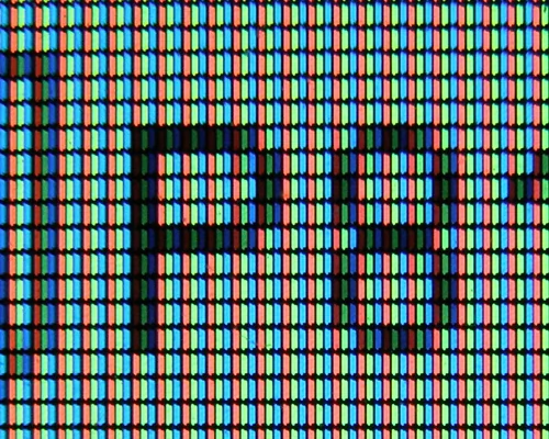
Computers represent various colors by mixing together four color channels: Red, Green, and Blue for colors and Alpha for transparency (you will see this called RGB colors or RGBA). This is because a physical pixel on your screen is actually made out of three tiny lights: one that's red, one that's green, and another one that's blue.
Pixels on a computer display captured really close up.
In Godot shaders, these values range between 0.0 and 1.0. If the Red channel is 0.0, then the red light is turned off. If it's 1.0, the red light is fully turned on.
This means that each color can be represented by a floating point value. You can define each value as a float in the fragment shader:
voidfragment(){float red =0.0;float green =0.0;float blue =1.0;float alpha =1.0;
COLOR =vec4(red, green, blue, alpha);}
In this code:
Red is turned off
Green is turned off
Blue is fully turned on
Alpha is fully turned on, meaning the color is completely opaque
While this works, these four values all describe a single color, so it makes sense to keep them together. The GDShader language allows you to group up to four numbers inside of a vector:
voidfragment(){vec4 portal_color =vec4(0.0,0.0,1.0,1.0);
COLOR = portal_color;}
Pretty numbers like 1.0 and 0.0 make for great examples, but often produce colors that look artificial.
This doesn't only apply to colors. Most effects will look more natural with "imperfect" numbers.
Try experimenting with each color channel of your portal_color variable! Reduce the blue a little and mix in a touch of red and green. Godot will recompile the shader and update it in the viewport as you make changes.
OldDew
Teacher at GDQuest
Before we continue programming our shader, there's one more essential feature in shader programming languages that I want to cover. This COLOR variable that we used is called a shader built-in, and this is how you get context from the graphics card or write the output. There are more built-ins available, including several we will need to complete the portal.
Can I access individual values inside a vector?
Yes, GDShader provides two equivalent ways of accessing vector components: r, g, b, a and x, y, z, w.
In our example, portal_color.r would return the red component of the color as a float. If you write portal_color.x, the same thing happens.
The two notations exist because vectors are commonly used to represent both colors and positions. Accessing the x channel of a color would be quite confusing, so when working with colors, it's better to use rgba. Likewise, for positions, it's good practice to use xyzw.
You're not limited to a single component. One of the most useful vector features is swizzling: rearranging and accessing multiple components of a vector at once.
For example, portal_color.rgb returns a vec containing the red, green and blue components, while portal_color.bgr returns the same components in reverse order. You can even repeat components, such as portal_color.rr. This creates a vec2 where every value is the red component.
Important to note is that you can't swizzle using different notations between components. For example, portal_color.xrya is invalid because it uses both positional (x, y) and color (r, a) notations.
Why is this data type called vec4 and not color?
In programming languages that give you more control over the output or the program's performance, the data types are usually named based on what is actually stored in the computer's memory.
As we saw, on the graphics card, a color is a series of four numbers. In math, a vector is a series of numbers. A vector is not limited to two or three dimensions, and it can represent more than just coordinates on the screen or on a grid. For example, colors!
That's why the data type is called vec4: a series of four numbers.
7. Shader built-ins
Built-in variables are the bridge between you and the GPU.
Some let you get context from the GPU. For example:
TIME: The time since the engine has started
VERTEX: The position of the current vertex
UV: The coordinates of the current pixel relative to the drawing area
Others let you send instructions to the GPU:
COLOR: Tells the GPU what color to apply to the current pixel (when used in the fragment() function)
VERTEX: Tells the GPU the new position of the current vertex (only when used in the vertex() function)
Take a mental note that every built-in always refers to the current pixel, vertex, or piece of data being processed. This tiny detail makes a huge difference when it comes to the way you need to approach shader programming.
OldDew
Teacher at GDQuest
Why can VERTEX both get and provide context to the GPU?
Some built-ins allow you to both get and provide information to the GPU depending on where you use the variable. The vertex shader (i.e., writing code in the vertex() function) lets you both read from and write to the VERTEX variable to use or change the position of the vertex being processed.
Some built-ins only let you read them, like the TIME variable.
To see a list of all fragment shader built-ins and their behavior, check the official documentation.
Pay attention to the in, out, and inout qualifiers. They tell you whether a built-in is read-only, write-only, or whether it allows both operations.
Available built-in variables and their behavior change between the vertex and fragment shaders!
A common mistake when getting started with shaders is using the built-in variables in the wrong shader function. You need to be aware that some built-ins are available only in one function. Worse, others can be used in both the vertex and fragment shaders, but their meaning changes depending on where you use them!
Let's take the VERTEX built-in as an example:
When used inside a vertex shader, it refers to the current vertex position, relative to the center of the sprite.
When used in a fragment shader, it's the position of the pixel on the screen.
That's pretty confusing! What's important here is not to memorize the specific behavior of VERTEX, but to be aware of the shader stage a built-in variable belongs to when reading the official documentation.
Now that you understand how the shader colors every pixel, we can move on to shaping the portal. As a reminder, this is what the final result looks like:
The Blue Portal
If you ignore the wobbling and distortion, the overall shape of the portal looks like a circle.
But there's an interesting problem. You've just learned that the same fragment function runs for each pixel in parallel. If every pixel executes the exact same code, how can we tell the GPU to draw a circle?
We need some pixels to be part of the circle while others should remain transparent.
While the code is the same for each pixel, the input values are not. To decide whether a pixel should be part of a circle, we just need to know where that pixel is. Depending on the pixel's position, we draw it or not. That's how you draw procedural shapes in shaders!
Godot gives us this information through the UV built-in variable.
8. The UV built-in
The UV built-in is a vec2 variable that stores the position of the current pixel as a pair of normalized coordinates. This means that both the horizontal and vertical components range from 0.0 to 1.0, where vec2(0.0, 0.0) is the top-left corner of the sprite and vec2(1.0, 1.0) is the bottom-right corner.
Because of this, the actual node size doesn't matter: a UV coordinate of (0.2, 0.5) always means "20% from the left and 50% from the top", whether the sprite is a tiny, 64x64 icon or a massive 1024x1024 image.
But how can you know if a pixel sits at any given coordinate? Since a shader runs in parallel for every pixel, you can't print values like you would in GDScript with the print() function. That would flood the console with thousands of messages. Instead, you visualize values as colors.
Take the horizontal coordinate of the UV vector and assign it to the red channel of the COLOR built-in to get a gradient ranging from black to red. Replace your fragment() function with this code:
voidfragment(){
COLOR =vec4(UV.x,0.0,0.0,1.0);}
This visualization reveals an interesting fact about the x coordinate. The left side of the gradient is black. With no added color, it means that UV.x is 0.0 at the shader's left side. On the other hand, the right side is a bright red. This is where UV.x grows to its maximum value of 1.0.
Let's repeat this experiment. This time, assign the vertical component to the green channel. Update your fragment() function like this:
voidfragment(){
COLOR =vec4(0.0, UV.y,0.0,1.0);}
The gradient is black at the top of the shader. This reveals that UV.y is 0.0 at the top and increases to 1.0 toward the bottom. In GDShader, just like in 2D scenes, the Y coordinate of the UV built-in increases when going down.
Now, let's combine and visualize both components of the UV vector at once. Edit the code to visualize both the x and y components of the UV:
voidfragment(){
COLOR =vec4(UV.x, UV.y,0.0,1.0);}
Here is how you can interpret the UV properties by looking at how the colors are laid out:
Top-left is black because both UV.x and UV.y are 0.0.
Top-right is red because UV.x reaches 1.0 and UV.y is still 0.0.
Bottom-left is green because UV.y reaches 1.0 and UV.x is still 0.0.
Bottom-right is yellow because UV.x and UV.y both reach 1.0.
But the most important things to remember about UVs are that:
UVs are normalized coordinates that tell you the position of a pixel relative to the sprite's bounding box.
UV.x increases from left to right.
UV.y increases from top to bottom.
The UV origin coordinate vec2(0.0, 0.0) sits in the top-left corner of the sprite's bounding box.
The UV coordinate vec2(1.0, 1.0) sits in the bottom-right corner of the sprite's bounding box.
The idea of visualizing values as colors isn't limited to UV coordinates. It's one of the main tools we use to inspect and debug shaders.
In GDScript, you would use the print() function or the Debugger. In shaders, you preview the output as colors and interpret it.
Whenever you're trying to understand a built-in variable, a function, or the result of a mathematical expression, try turning it into a color first. It often reveals patterns that are hard to anticipate otherwise.
Next, let's use UV coordinates to draw a circle.
OldDew
Teacher at GDQuest
Get an in-depth look at how UVs work in shaders
UVs are among a shader artist's most commonly used tools.
For a more detailed overview of UVs, check out and bookmark this free library entry: Shader UVs
9. Drawing a circle
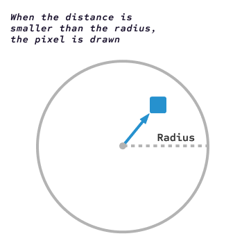
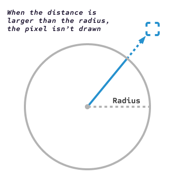
For a pixel to be inside of a circle, its distance from the center needs to be smaller than the radius of that circle.
A pixel inside the circle being coloredA pixel outside the circle not being colored
Apply this rule to all pixels, and you'll end up coloring the whole circle.
The portal we want to create is right in the middle of the shader region. Since UV coordinates range between 0.0 and 1.0, the middle becomes a point with the coordinates vec2(0.5, 0.5).
You can calculate the distance between every pixel and that point using a built-in shader function: the distance() function. It returns the distance between two points. For example, distance(vec2(0.0, 0.0), vec2(1.0, 0.0)) returns 1.0.
We can calculate the distance between the center point vec2(0.5, 0.5) and the current UV coordinates. If that distance is smaller than a target radius, then the pixel is inside the circle. Otherwise, it's outside the circle.
Visualizing the distance
Before jumping into making the comparison, let's visualize the result of calling distance(). Save the result in a distance_from_center float variable and place it in any of the final color channels.
In the following code example, I assigned the distance_from_center to all three RGB channels. When we do that, we produce a grayscale image, which is easier on the eyes. Update the fragment() function in your shader file by typing in the following code and visualize the result:
voidfragment(){vec2 center =vec2(0.5,0.5);float distance_from_center =distance(UV, center);
COLOR =vec4(
distance_from_center,
distance_from_center,
distance_from_center,1.0);}
What do you see, and how do you interpret the output? Take a moment to try and make your own observations. Read on for my interpretation.
We can see that the center of the image is black, and as we move toward the edges and corners of the sprite, the color gradually gets lighter up to a light gray.
The pixels near the center don't add any color since the distance between their UV coordinate and the vec2(0.5, 0.5) point is close to 0.0. As we get closer to the edges, the distance increases, so the value gets higher, and that's why pixels get brighter.
Turning the distance gradient into a circle
To turn the distance gradient into a clean-cut circle, you need to make a decision. Pick any radius value, like 0.1, store it in a float and compare it to the distance from the center:
If it's smaller, the pixel is inside the circle, so the COLOR is set to blue.
Otherwise, the pixel is invisible, which means its alpha value is 0.0.
Let's update the shader code. Reintroduce the portal_color variable, add a new variable representing the desired radius of the circle, and let's use an if and else condition to draw some pixels blue and leave others transparent. Update your fragment() function to use these variables:
voidfragment(){vec4 portal_color =vec4(0.23,0.35,0.65,1.0);vec2 center =vec2(0.5,0.5);float distance_from_center =distance(UV, center); COLOR =vec4( distance_from_center, distance_from_center, distance_from_center,1.0);float radius =0.1;if(distance_from_center < radius){ COLOR = portal_color;}else{ COLOR =vec4(0.0);}}
Why is the background checkered?
Godot and many other graphical applications represent transparency with a checkered texture.
This makes transparent areas easy to distinguish from solid colors and prevents them from being mistaken for part of the image.
In this example, we still calculate the distance from the center like before. If the distance from the center is less than the radius value, we set the output COLOR to our portal color. Otherwise, we set it to a fully transparent color, which will make the pixels transparent.
It seems we could've picked a better value for the portal radius. The current value of 0.1 is too small.
Instead of going back to the code and replacing it every time we want to try a different size, let's make the radius adjustable in real time and from game scripts with the help of shader uniforms.
Code Reference: res://portal.gdshader
This is what your portal shader should look like at this point with the circle drawing code:
shader_type canvas_item;voidfragment(){vec4 portal_color =vec4(0.23,0.35,0.65,1.0);vec2 center =vec2(0.5,0.5);float distance_from_center =distance(UV, center);float radius =0.1;if(distance_from_center < radius){
COLOR = portal_color;}else{
COLOR =vec4(0.0);}}
GDShader control flow syntax
Like most other languages, GDShader supports control flow elements like if statements, for loops and while loops.
If you're coming from GDScript, the biggest syntax difference is that control flow blocks are enclosed in curly braces ({}) instead of being defined by indentation, like all code blocks in this language.
A for loop going from 0 to 10 is written like this:
for(int i =0; i <10; i++){// ...}
Its structure is made out of three regions:
Initialization: int i = 0 sets the starting value of the integer i to 0.
Comparison: i < 10 compares the value of i with 10 at every loop iteration. When the condition becomes false, the loop execution stops.
Increment: i++ adds one to i after every loop iteration.
Finally, a while loop looks like this:
while(condition){// ...}
Built-in functions
On top of built-in variables, Godot also provides a large set of built-in functions serving all kinds of purposes like maths and texture-related utilities.
We have just used the distance() built-in function, which calculates the distance between points, but there are more built-in functions available. You can check out the full list in the Godot Documentation.
Doesn't a vec4 take four parameters?
Normally, yes. A vec4 stores four values, so you'll usually write something like:
vec4(1.0,0.0,0.0,1.0)
For convenience, Godot lets you construct vectors with fewer values. When you pass a single number to vec4, it copies that value into every component. So these two lines of code are strictly equivalent:
vec4(0.0,0.0,0.0,0.0)vec4(0.0)
In this shader, we use vec4(0.0) to create a fully transparent black pixel. Since the alpha component is 0.0, the other values don't matter as they'll be invisible anyway, so the values of the RGB components don't make a difference here.
Isn't it bad to use if statements inside shaders?
If you know a little about shaders, you might have heard that you should never use conditions inside shaders to improve performance.
It might have been true in the past, but it's not a problem now. Simple if statements and conditions that check uniform variables (we will see what those are soon) are generally safe to use. Even in cases where the compiled shader code would produce a branching structure, it can be worth it if the condition skips a large part of the code.
So, you should not try to always avoid if statements in shaders. It's a good idea to measure the performance of different versions of the code or read the compiled shader code to avoid making incorrect assumptions, just like with all performance-related things.
You can read more on GPU conditionals in this article from veteran graphics programmer Inigo Quilez: GPU conditionals.
10. Editable properties with uniforms
Uniforms are variables whose values come from outside the shader. Much like exported variables in GDScript, they appear in the Inspector and can also be changed from code or animations.
This is an example of a uniform that allows controlling the radius from the editor
You declare uniforms near the top of the shader outside of any function. The syntax looks like this:
uniformfloat variable_name;
First, you type the uniform keyword, then the type (floatfloat in this case), and finally the name of the variable (variable_name).
So far, we hard-coded the circle radius to 0.1, which means changing it required editing the shader. Let's replace that constant with a uniform so we can experiment with different values directly in the inspector. Update your shader code as follows:
shader_type canvas_item;uniformfloat portal_radius;voidfragment(){vec2 center =vec2(0.5,0.5);float distance_from_center =distance(UV, center);float radius =0.1;if(distance_from_center < radius){if(distance_from_center < portal_radius){ COLOR =vec4(0.23,0.35,0.65,1.0);}else{ COLOR =vec4(0.0);}}
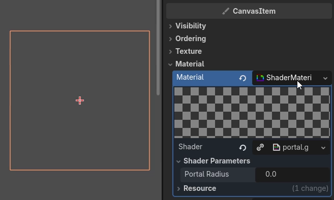
Godot automatically adds the shader property in the Inspector tab under MaterialMaterialShader Parameters. Click and drag the property to increase the radius of the portal.
Increasing the radius uniform
Live editing is already much more convenient, but there are still a couple of rough edges.
First of all, it's strange that the portal starts invisible and has a radius of 0.0.
Secondly, the Inspector accepts any floating-point value, even though anything larger than 0.5 starts pushing the portal outside of the sprite's bounding box.
The hint_range hint communicates the intended value range to the Inspector. This limits the value between 0.0 and 0.5 and creates a slider ranging between the edges of the interval. And the assigned number, 0.2, is the uniform's default value.
The interactive examples throughout this guide expose shader uniforms as slider controls as well, so you can experiment with shader parameters directly in the browser.
To get the most out of the guide, you should always type the shader in the Godot editor yourself (don't just copy and paste).
Try moving the Portal Radius slider and watch the circle grow and shrink.
OldDew
Teacher at GDQuest
Portal Radius
Code Reference: res://portal.gdshader
This is the complete portal shader code so far:
shader_type canvas_item;uniformfloat portal_radius:hint_range(0.0,0.5)=0.2;voidfragment(){vec2 center =vec2(0.5,0.5);float distance_from_center =distance(UV, center);if(distance_from_center < portal_radius){
COLOR =vec4(0.23,0.35,0.65,1.0);}else{
COLOR =vec4(0.0);}}
Before moving on, take a moment to appreciate how much you've learned already:
Shaders run in parallel. You write a program for one pixel, and then the GPU runs it for every pixel at once.
The COLOR built-in lets you decide what color a pixel should be.
The UV built-in gives you the coordinates of a pixel.
The distance() function tells you the distance between two points.
To inspect and debug shader code, we visualize values as colors.
Uniforms let you control shader parameters without changing the shader code.
It's a surprisingly long list considering we only drew a circle, but we already learned some of the foundational techniques you will use to create 2D shader effects from here on.
The rest of this guide will show you how to build upon these foundations. We will keep using these same ideas in different ways, and whenever we encounter a new problem, we will look for another tool in Godot's shader toolkit.
OldDew
Teacher at GDQuest
Our circle currently has a jagged outline, something that we call aliasing. This may be subtle or hard to spot on your display, but we want to avoid it. In general, we want to control how smooth the edges and transitions between effects are.
There's a commonly used shader function that's a good tool for smoothing: the smoothstep() function. We will learn about this next.
My circle is squashed
If in your project the circle is squashed, it means that your Sprite2DSprite2D node is not a perfect square. For example, this is how the same shader behaves with a sprite that has a size of 400x200px:
Portal Radius
This behavior is driven by how UVs behave. Both UV.x and UV.y range between 0.0 and 1.0. In other words, they both represent percentages of their respective axes.
On a 400x200 canvas, a distance of 0.1 along the x-axis represents 40 pixels, while the same distance along the y-axis represents only 20 pixels. Since we use the same value for both axes, the circle covers twice as many pixels horizontally, making it appear stretched.
To draw a circle on a non-square canvas, you need to account for its aspect ratio so that UV values correspond to equal distances in pixels.
What is the shader_type keyword for?
I haven't mentioned it yet, but you probably noticed that the first line of the shader uses the shader_type keyword:
shader_type canvas_item;
This tells Godot that the shader will be used for a 2D node, like a Sprite2DSprite2D or a TextureRectTextureRect. Canvas item is the base type for all the nodes that draw in 2D in the engine.
When we created the shader, Godot inserted this line based on the Mode that we picked in the creation dialog.
If you want to use a shader for a different purpose, you need to use a different shader type. Here are the four other most common types:
spatial, for 3D objects
particles, for particle systems
sky, for sky rendering
fog, for volumetric fog effects
Are there other uniform hints?
Yes, there are also hints for colors, enumerations, integers, and textures. You can find all available hints in the official documentation: GDShader Uniform hints.
There are two notable hints:
source_color is for vec3 and vec4 variables. It tells the Inspector to display a color picker.
hint_enum("String1", "String2") is for intint variables. It displays a dropdown widget in the editor. It works like an enum in GDScript: if you pick String1, the value is 0, and if you pick String2, the value is 1, and so on. You can use it to define different modes for the shader.
The hint that we used for the circle radius, hint_range(min, max, [, step]), is not limited to floatfloat variables. It also works with intint variables.
11. Drawing smoother shapes with smoothstep
If you take a closer look at the circle, you'll notice it's rough around the edges. This is because a pixel is either blue or fully invisible. The shader doesn't produce any in-between values to create a smoother transition between the circle and the background.
To solve this issue, GDShader provides the smoothstep() function. You use it like this: smoothstep(edge0, edge1, x). When edge0 is smaller than edge1, this returns:
0.0 if x is below edge0.
1.0 if x is above edge1.
A smooth in-between value when x is between both edges.
It's difficult to wrap your head around it with numbers. It's much better to visualize the function's output, so let's do that.
The shader example below runs the smoothstep() function over the coordinate UV.x. Try moving the uniform sliders to get a sense of how the smoothstep() function works.
Edge0
Edge1
shader_type canvas_item;uniformfloat edge0 :hint_range(0.0,1.0)=0.3;uniformfloat edge1 :hint_range(0.0,1.0)=0.7;voidfragment(){float result =smoothstep(edge0, edge1, UV.x);
COLOR =vec4(vec3(result),1.0);}
What do you observe? When Edge0 and Edge1 are farther apart, you get a wider gradient. Outside of this range, you get pure white or pure black.
If you get the two edges very close together, you get a thin smooth border. Now, instead of running smoothstep() for the horizontal coordinate UV.x, let's try applying it to the distance() function we used to draw the portal.
Update your shader code to the version below. It uses two uniform values and the smoothstep() function instead of a single radius. This removes the need for a conditional block:
Edge0
Edge1
shader_type canvas_item;uniformfloat edge0:hint_range(0.0,0.5)=0.4;uniformfloat edge1:hint_range(0.0,0.5)=0.41;voidfragment(){vec2 center =vec2(0.5,0.5);float distance_from_center =distance(UV, center);float portal =smoothstep(
edge0,
edge1,
distance_from_center
);
COLOR =vec4(vec3(portal),1.0);}
Why did you name the new variable portal?
Because shader code runs in parallel, it's common to name variables after the shapes they produce.
In this shader, we are working toward drawing a portal, so we name the variable portal, even if for now the shape the portal variable produces is a circle.
Once you apply the code to your shader in Godot, you will see that this produces black and white. This gives us an idea of the output, but the values we're generating don't have to represent color.
You can use them with any channels, for example, to control transparency: we can use smoothstep() as a transparency mask.
Instead of putting the result in the RGB color channels, apply it to the alpha channel while keeping the portal's blue color constant. Update your shader code to use the portal shape for the final color's alpha channel:
Edge0
Edge1
shader_type canvas_item;uniformfloat edge0:hint_range(0.0,0.5)=0.4;uniformfloat edge1:hint_range(0.0,0.5)=0.41;voidfragment(){vec2 center =vec2(0.5,0.5);float distance_from_center =distance(UV, center);float portal =smoothstep( edge0, edge1, distance_from_center
); COLOR =vec4(vec3(portal),1.0);vec3 portal_color =vec3(0.23,0.35,0.65); COLOR =vec4(portal_color, portal);}
Now, we are preserving the blue color, but something is off: the center is empty and the outer edges of the sprite are blue!
This happens because smoothstep() returns 0.0 for pixels inside the circle and 1.0 for pixels outside the circle. Since we're using that value for the alpha channel, those pixels become fully transparent. There are two ways to fix this.
Flipping a mask with subtraction
One solution is to subtract the result of calling smoothstep() from 1.0. It inverts the overall result. For example, when you subtract 0.0, you get: 1.0 - 0.0 = 1.0. When you subtract 1.0, you get 1.0 - 1.0 = 0.0. In shaders, we often invert values like that to flip transparency masks.
Try updating the lines that calculate the circle shape like this:
voidfragment(){vec2 center =vec2(0.5,0.5);float distance_from_center =distance(UV, center);float portal =smoothstep(float portal =1.0-smoothstep( edge0, edge1, distance_from_center
);vec3 portal_color =vec3(0.23,0.35,0.65); COLOR =vec4(portal_color, portal);}
It will restore the blue circle at the center of the sprite. This is a very commonly used trick in shaders.
Flipping the function parameters
In this case, we don't need to invert the mask with subtraction, though. Revert the change in your code.
Then, if you haven't already, try dragging the Edge0 slider past Edge1 and watch what happens.
Did you notice the shape flip? It turns out smoothstep() doesn't require edge0 to be smaller than edge1. Swapping the two edges reverses the result, which is exactly what we need. You could also swap the function arguments like this:
When you're learning a new function, don't be afraid to push its parameters beyond what you think is "correct". Unexpected behavior is often the quickest way to understand what the function is really doing.
OldDew
Teacher at GDQuest
Isn't swapping the function arguments or values undefined behavior?
Swapping the arguments of the smoothstep() function isn't undefined behavior. The math behind it supports inverting the parameters.
More generally, don't worry about experimenting with shader functions because a shader will not crash even with an invalid calculation like dividing by zero. Here's an example of a shader that divides by zero (like all other examples in this guide, it's a real shader running live in your browser).
As you can see, this code runs without crashing:
voidfragment(){
COLOR.rgb =vec3(1.0/0.0);}
Incorrect shader code may produce unwanted visual glitches, but it will generally not crash. Similarly to Godot and GDScript, shader code often tries to handle invalid operations gracefully and keep the program running on the graphics card.
So, you should not worry about experimenting with numbers and operations and risking too many code errors or crashes.
Take a look at how the portal looked before versus how it looks after we added a soft edge. The difference may be hard to see, depending on your screen's resolution. Look for jagged edges on the version on the left:
Improving the controls
While the circle looks smoother now, its controls could be improved. Before, when you wanted to increase the radius, you just had to adjust a single radius value. Now, not only do you have to change two edges, but you also need to keep track of how far apart their values are to keep the portal softness the same.
A better way to implement this is by making them relative to one another: keeping the radius value and adding a softness uniform. Update your code to reintroduce the radius uniform and add a new softness uniform:
Notice how it is much easier to control the portal. Before, if you wanted to change the size of the circle, you had to change two variables.
Now, the inner edge turned into radius - softness. This makes it always have a fixed distance from the outer radius. You no longer need to worry about two radii when changing the portal's size or softness.
Now that we're able to draw smooth circles, we're ready to take on the next goal: giving the portal an outer ring.
When working on shaders, or any game code for that matter, you want to make editable parameters relevant and intuitive whenever possible.
With shaders, you can often improve uniforms by making the outlines, softness, glow, and other similar effects relative to the shape they extend or surround. Just like we did with the radius and softness uniforms.
12. Creating a ring with masks
Let's take a look at the effect we want to achieve again:
The Blue Portal
The portal is made out of two main parts: its dark center and a ring-shaped rim separating it from the outside world.
Instead of creating a new shape from scratch, you can reuse the circular shape by carving a smaller circle out of it. The process of hiding part of an image is called masking.
First, take the original circle and rename its radius uniform to radius_outer:
uniformfloat radius:hint_range(0.0,0.5)=0.4;uniformfloat radius_outer:hint_range(0.0,0.5)=0.4;uniformfloat softness:hint_range(0.0,0.2)=0.01;voidfragment(){vec2 center =vec2(0.5,0.5);float distance_from_center =distance(UV, center);float portal =smoothstep( radius, radius - softness,float mask_outer =smoothstep( radius_outer, radius_outer - softness, distance_from_center
);vec3 portal_color =vec3(0.23,0.35,0.65); COLOR =vec4(portal_color, portal); COLOR =vec4(vec3(mask_outer),1.0);}
In this code, notice that we temporarily stop using the portal_color variable to preview the mask instead. This is the traditional way to experiment with shaders. We visualize the changes we make by changing the output COLOR values.
Now, add a radius_inner uniform and a second smoothstep() call to generate a smaller circle. The call is the same as the outer circle's, except that it uses the new, smaller radius:
Our code now produces two circles, a larger and a smaller one. We can subtract the inner circle mask from the larger circle mask to create the ring shape we are looking for. Add a new variable to calculate the mask for the portal rim:
Remember: smoothstep() returns either 0.0, 1.0 or an in-between value.
Wherever the two masks have the same value, subtracting one from the other results in 0.0. Since the smaller circle is entirely inside the larger one, subtracting the smaller circle from the larger one turns the center area into 0.0. This leaves only the rim visible.
You just learned how to create and combine masks!
A mask is simply a number that tells you how strongly an effect applies at the current pixel.
A mask value of 0.0 means "do not apply the effect". 1.0 means "apply it fully", and anything in between creates smooth transitions.
The masks in this example happen to produce a ring, but you can overlap and combine as many masks as needed to create complex shapes.
Note that masks aren't limited to drawing shapes. They can control virtually any effect. For example:
Revealing or hiding parts of a texture
Blending colors
Applying effects only to selected regions
We will use masks for blending colors and applying effects only to certain regions later in this guide.
OldDew
Teacher at GDQuest
Coloring the masks
We are only visualizing one mask with the color variable, but we actually have a mask for the full circle, the larger circle, and the smaller one, as well as the rim. How do we color all that? Well, first, let's use our mask for the rim to display a color.
How? By using the portal_color and the mask for the rim together! We can use our "black and white" rim mask as the alpha channel to only draw the rim and discard the black pixels.
Edit the COLOR output to use the portal_color for the RGB channels and the mask for the rim for the alpha channel:
voidfragment(){// ...float mask_rim = mask_outer - mask_inner; COLOR =vec4(vec3(mask_rim),1.0); COLOR =vec4(portal_color, mask_rim);}
With that, the shader draws the ring we've seen in the experiment, but now using the portal's color and uniforms.
Radius Outer
Radius Inner
Softness
That's one way to draw a ring shape in shaders: by subtracting two circles. More generally, you can subtract two masks of the same shape to generate a procedural stroke or outline.
When adding our second circle, we introduced a uniform that's not so intuitive to use. You have to move two sliders to shape the ring, and the output is invisible when the inner radius is larger than the outer one. Let's simplify the uniforms before moving on.
Simplifying the uniforms
What do we want to control in our portal? Only the rim's thickness and the overall radius. We can change the uniforms to express the rim in terms of its overall thickness.
Replace the radius_inner uniform with a new rim_width uniform and update the calculation. While we're at it, let's also go back to naming the overall shape's radius just radius:
You create a shader by narrowing it down to its building blocks. But once those blocks are in place, it's good practice to combine them into meaningful components.
Your final portal shouldn't be a collection of circles, vectors and arbitrary numbers. Instead, it should behave like a real object with properties such as its rim, its color, its interior or its size. These are the controls you'll want to adjust later, and the ones other people will understand immediately.
Don't do this too early!
Focusing on naming and nailing the shader uniforms can distract you from the problem in front of you. Allow yourself to use shapes with no real meaning when experimenting, just like we did with the two circles. At this stage, your goal is to make the effect work and not to design nice parameters.
Once you're happy with the result, take a second pass to clean it up. Rename variables, group related concepts, and expose controls that describe the effect instead of how it's implemented. As the shader grows, you may even find yourself revisiting some of those controls again.
Shader development is iterative. Designing a good interface is yet another iteration.
OldDew
Teacher at GDQuest
Code Reference: res://portal.gdshader
At this point, your shader should have the following code:
So far, we've only worked with a single color and mask. But to sell the illusion of our portal being a gateway to another place, we need both a lighter rim and a darker center, each with their own appearance.
But how can we use multiple shapes and colors at once exactly?
The answer is surprisingly simple. We can apply each mask that we generated to a different color to stack the shapes. The rim's mask doesn't include the inner circle's mask. Since these masks do not overlap, we can tint each one independently and add the results together.
We apply one color to each mask by multiplying a color and a mask together. We then add the results to get multiple colors:
This works because a mask is just a floating-point value between 0.0 and 1.0. Multiplying a color by a mask scales its intensity:
The regions in which the mask is 0.0 make the color disappear.
Regions of the mask that are 1.0 make the color fully visible.
Values in between produce a smooth transition between colors.
Update the shader to add the two color uniforms, combine the masked colors into final_color, and use it as the output color. Each part of the portal is made from two ingredients:
A color, which we'll expose as a uniform so it can be customized.
A mask, which determines where that color appears.
The final color controls how the portal looks, but it's the alpha channel that decides which parts are shown and which are thrown away.
Currently, alpha is set to the rim mask, which doesn't cover the inner region of the portal. You need a mask that covers both the rim and the center so that only the outside region of the portal turns invisible. One of the masks we used already has that property: the outer mask.
As opposed to the ring, the outer mask's center is filled. Replace the alpha channel of the final color with the outer mask to reveal both the rim and the center of the portal:
voidfragment(){// ...vec3 final_color = mask_rim * color_rim + mask_inner * color_inner; COLOR =vec4(final_color, mask_rim); COLOR =vec4(final_color, mask_outer);}
Radius
Rim Width
Softness
Color Inner
Color Rim
At this point, the portal is no longer a single colored shape. It's built by combining multiple layers, each responsible for a different part of the final image:
Masks determine where each part appears.
The alpha channel defines the portal's silhouette.
Colors determine what each part looks like.
One great thing about shaders is that you can get different visuals just by changing a few inputs.
You could've drawn this portal, but the moment you wanted to change its shape, color, or style, you'd have to create a new variant.
You can produce completely new visuals by changing the shader's inputs.
Thin Purple Portal
Radioactive Portal
OldDew
Teacher at GDQuest
We've already learned quite a bit about shaders, but the result is still a little underwhelming as it is static. Next, we will learn how to make our shader move.
14. Animating the portal with periodic functions
A portal isn't just a boring geometric shape; it's a rift in space and time. A rupture in the world's very fabric. A door to the unknown.
What this should look like comes down to imagination. You could picture the portal and its boundaries constantly fighting with the world around it to keep itself open. Let's create that feeling by introducing movement and irregularity.
Controlling the aesthetic with shaders
When designing effects, it's a good idea to consider the world they live in and its rules.
The distorted portal we're creating will work for a space game, but for an underwater world, a vortex-shaped portal would be a better fit.
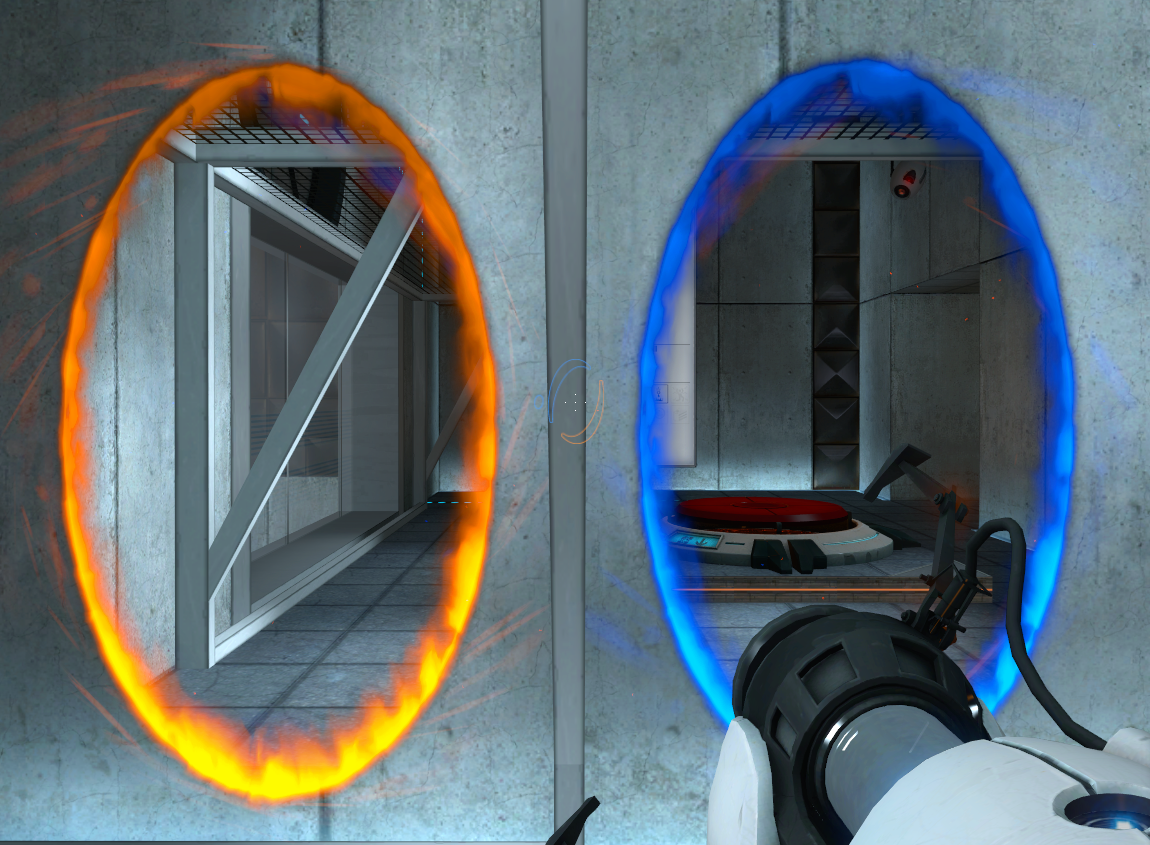
Another great example is the portals from the Portal series. In that game, you control a test subject in a white, sterile laboratory. The portals are vertical, matching the height of the character, and their outer edges form an almost perfect ellipse.
Both portals from the Portal series
The right look for a given effect will be different from game to game, depending on the game's universe and art direction. While you could use shaders found online as assets, understanding shader programming gives you more control over the final look.
Before we introduce motion, let's think about what actually makes the portal perfectly round.
The shader measures the distance between the sprite center and every pixel. We use that distance to determine whether the pixel is inside or outside the circle.
How do we change the shape and make it irregular then? We modify that measured distance for every pixel. Before we do that, let's look at what happens if we add or subtract 0.1 from this distance, because the effect can be counter-intuitive.
Adding and subtracting from the distance
Try changing the distance_from_center variable by first adding to it. What do you notice?
Adding 0.1 to the distance makes the portal smaller
Subtracting 0.1 makes it larger
By adding 0.1, every pixel behaves as if it were farther from the center than it actually is. As a result, pixels reach the radius threshold sooner, causing the portal to appear smaller. Subtracting 0.1 has the opposite effect.
Can you explain this in greater detail?
We can better understand what's happening with a tiny bit of math. Before adding 0.1 to or subtracting 0.1 from the distance, the pixel was considered inside the portal if the distance was less than the radius:
distance < radius
Adding 0.1 to the distance changes the comparison into:
distance +0.1< radius
This works like an equation, and we can move the 0.1 term to the right of the equation by subtracting 0.1 from both sides. This is equivalent to the previous equation:
distance < radius -0.1
This shows that adding to distance has the same effect as reducing the radius!
Making the portal breathe
We can use this property we observed to make the portal breathe. We will make the portal grow and shrink. This will introduce not only how to animate a shader, but how to make an animation loop seamlessly.
In Godot shaders, we use the TIME built-in to animate values over time. TIME is a number that increases constantly: it gives us the time since the engine started.
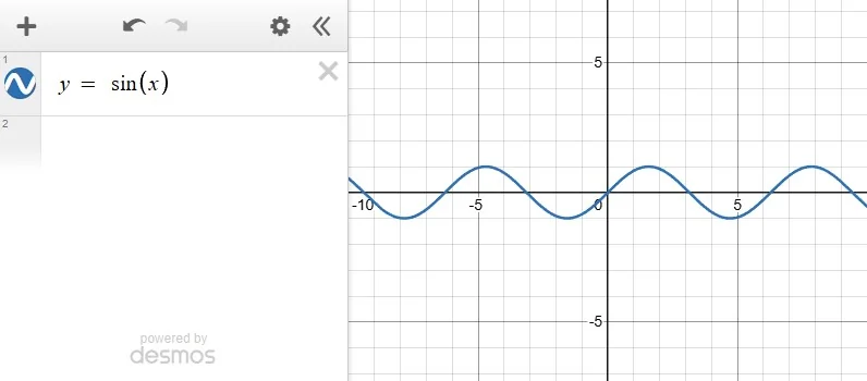
To animate the portal, we need a value that doesn't increase forever. Instead, we need a number that oscillates between positive and negative values. We can use periodic functions like sin() and cos() to achieve this. As their input value increases, their output oscillates indefinitely between -1.0 and 1.0.
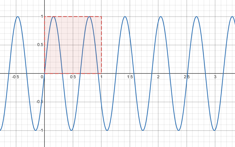
This graph shows the output of the sin() function as its input value increases:
In this editor, you write equations, functions and variables in the left column, and they draw in the graph on the right. You can learn more in the platform's Getting Started guide.
Update the distance calculation by adding sin(TIME) to it. To make the output range between -0.1 and 0.1, we multiply sin(TIME) by 0.1. Multiplying by a number between zero and one scales the result down. This gives you a breathing portal:
Because TIME is different in every frame, you can plug it into any mathematical function to create animations.
The sine function (sin()) takes a number as input and returns a value between -1.0 and 1.0. We call it a periodic function because as the input value increases, the output moves back and forth in a wave-like pattern between -1.0 and 1.0. This behavior is especially useful for repeating patterns like pulsing, waving, or bobbing.
This graph illustrates how sin(TIME) oscillates as the time value increases:
Many visual effects rely on values that continuously oscillate over time. There are many functions that produce this kind of motion, but the most commonly used ones are sin() and cos() (respectively, the sine and cosine functions). They generate smooth, repeating waves that oscillate between -1.0 and 1.0.
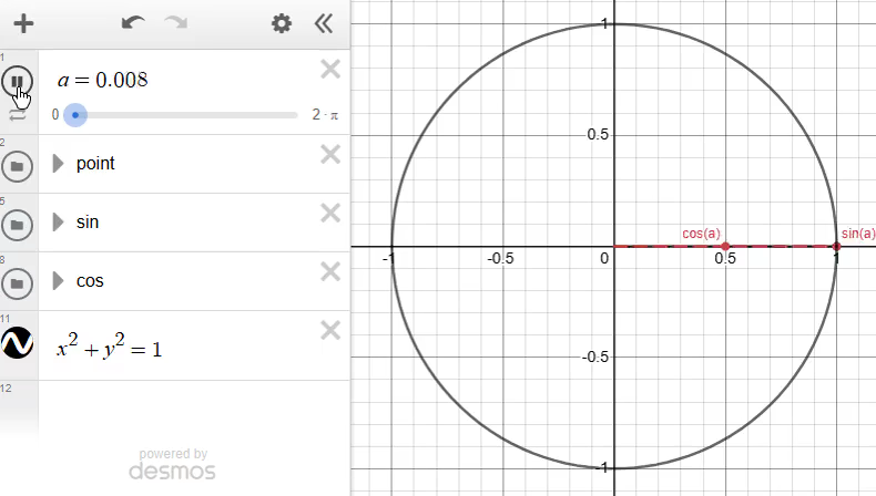
To understand why these functions produce waves, we have to understand their relationship to a circle. In this graph, we have a point moving at constant speed along the perimeter of a circle with a radius of one unit:
The sine is the vertical position of the point along the circle's perimeter. The cosine is the horizontal position of the point along the circle's perimeter.
How to control oscillating functions
You can change how fast, how strong or when an oscillation happens by tweaking:
Frequency: How fast the wave changes. Change it by multiplying the input of the function:
Amplitude: How strong, or tall, the wave is. Change it by multiplying the entire function:
Offset: The shift in the wave's position along its cycle. Change it by adding a value to the function's input:
Combine them to get a generic and customizable oscillating function:
When we multiplied sin(TIME) by 0.1, we reduced the effect's strength by decreasing the oscillation amplitude. To change how fast the portal breathes, replace TIME in the sine input with TIME * 10.0.
Let's make the animation configurable by defining a uniform ranging from 0.0 to 0.1. To make the effect more subtle, we can set its default value to 0.02. Update your code like this:
We learned how to animate the shader and make the animation loop by using periodic functions, but the shape is still perfectly round. Let's learn how to deform it next.
Deforming the shape
Right now, the only differentiating factor between pixels is their distance from the center: distance(UV, center). But when we shrink or expand the shape, all pixels follow the same rule, which scales the shape uniformly:
sin(TIME)* breathing_strength
To make the portal look more chaotic, you need to slightly change the behavior between pixels depending on some input value.
Let's experiment with a property we already know: the relative position of the pixel in the sprite: UV. We can use the UV.x coordinate to modify the output of the sin() function:
sin(TIME + UV.x)* breathing_strength
This causes a pixel with UV.x = 0.1 to return sin(TIME + 0.1) * breathing_strength, and another with UV.x = 0.7 to return sin(TIME + 0.7) * breathing_strength. This makes the shape change not only based on how much time has passed, but also on how far to the right pixels are in the sprite.
In this example, I've added UV.x to the TIME value when calling the sin() function, but the effect is hard to see.
Sine input offset by UV.x
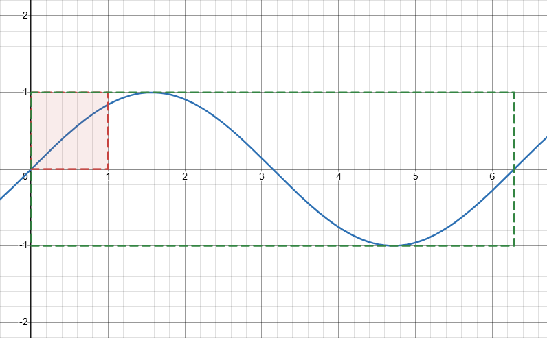
This is because UV coordinates range between 0.0 and 1.0. In that interval, the sine function doesn't complete a full oscillation; it takes 2πradians to complete one cycle (approximately 6.28 radians).
To increase the function's frequency, you need to multiply its input by a value larger than 1.0. For example, if we multiply UV.x by 10, the sine passes through more cycles across the width of the circle, which bends the shape.
This graph shows that if we multiply UV.x by 10, we get close to one and a half oscillations:
Here's what happens if we multiply UV.x by 10.0 when calling the sin() function:
sin(TIME + UV.x *10.0)* breathing_strength
Sine offset and UV.x scaled by 10.0
Let's briefly pause and place the latest experiment into the complete shader. Add a new variable in the fragment() function that has our oscillation and update the distance_from_center calculation to use it:
There's nothing special about this number; it's arbitrary. The number 10.0 produces just enough ripples for the animation to look interesting and for you to see the effect clearly.
However, there are a few special numbers we can use with periodic functions. You can use the number with the PI built-in. It is approximately 3.14 and represents the value at which sine completes half of a cycle.
If you multiply it by 2.0, you get the full cycle. This is used so often that Godot provides it as the TAU () built-in. Both in mathematics and in shaders, .
To get a full cycle inside a shader, you write sin(UV.x * TAU). Here's a visualization of this calculation's output:
voidfragment(){float cycle =sin(UV.x * TAU);
COLOR =vec4(vec3(cycle),1.0);}
The light band on the left shows the upper side of the sine wave, and on the right side of the image, the values go negative, which we cannot visualize directly as a color without extra calculations. The shader draws it as pure black, but values vary between -1.0 and 1.0.
You can multiply TAU by any whole number to get that many repeating cycles. This code produces two cycles:
voidfragment(){float cycle =sin(UV.x * TAU *2.0);
COLOR =vec4(vec3(cycle),1.0);}
Two oscillations
And this is what 10 cycles look like:
voidfragment(){float cycle =sin(UV.x * TAU *10.0);
COLOR =vec4(vec3(cycle),1.0);}
Ten oscillations
How to plot a function on the shader canvas as a graph
If you checked the question and answer above, you will have seen that we cannot visualize certain values directly as a color. There's a visualization technique that you can use to plot a value as a graph over your sprite.
In those cases, it's useful to draw the movement functions on top of your effect. Since the shader canvas is a 2D image, you can use the UV coordinates to plot the function.
In our shader, the function driving the oscillation is:
To plot it on the canvas, add an if statement that checks whether UV.y equals sin(TIME + UV.x * 10.0). If that's the case, draw a green pixel instead of the portal color.
Right now, the shader looks identical to the original. An image contains a finite number of pixels, so there's a very slim chance that the sine function will return a value that exactly matches the UV.y coordinate of one of them. Virtually no pixels pass our condition.
Replace the equality condition so pixels that are close enough to the function count as part of the line. Use a threshold of 0.04, which gives the function a visible thickness.
Notice how the effect gets morphed by the function shape. As the sine wave falls, the portal gets squished. As the wave rises, the portal grows.
You can now intuitively tell what changing the function will do. For example, increasing its frequency to 20 should make the portal rise and fall more often.
We can finally say the portal is no longer a circle. The more its breathing strength increases, the more strongly it wobbles left and right.
The pattern is quite predictable right now, but you can always increase the complexity by reshaping or adding more functions to the oscillation calculation.
Let's focus on changing that while leaving the rest of the shader unchanged. For instance, we can include both UV components in one wave or calculate two waves separately and add them together:
One diagonal wave
Two overlapping waves
In the first example, we use both coordinates in the same sine to obtain a wave that, added to the distance, makes the effect travel diagonally:
sin(TIME + UV.x *10.0+ UV.y *16.0)
On the other hand, the second example treats the vertical and horizontal components as totally separate waves and overlaps them.
sin(TIME + UV.x *10.0)+sin(TIME + UV.y *16.0)
Notice how it's harder to identify the pattern in the second example.
Function combinations in more detail
Addition is just one of many ways in which you can combine functions.
We could keep building this effect with sine waves for a long time.
We can:
Change their speed, strength, direction, and phase.
Layer more waves on top of each other.
Use other properties of the pixel, such as its angle around the center.
Each change gives us another kind of motion to experiment with.
Layering many waves at different scales
Using the angle around the center
This technique of creating an effect through code alone is also known as Procedural Generation (or "procgen" for short). It is often useful, especially when you want motion with a recognizable rhythm or direction.
However, if you're looking to create an effect which feels more chaotic, taking this approach can quickly require a fair amount of code and math. This can limit you in two ways:
The code can get hard to handle or too time-consuming to build in a small indie team.
The rendering performance cost can add up. Even if graphics cards are very powerful, they still need to run every operation for every pixel the shader needs to render.
Before reaching for procedural generation, there's a much simpler and faster way to add chaos. For that, we can sample textures.
OldDew
Teacher at GDQuest
15. Sampling and applying image textures
So far, we've described everything our shader does using mathematical expressions. But complex shapes and painted images are much easier to capture with an image that you apply to the sprite: a texture. Godot allows you to use textures inside of a shader.
Shaders read from textures through a process called texture sampling. In GDShader, you do that with the texture() built-in function. It takes two parameters:
The texture to be sampled
The coordinate from which to sample it
This example shows the code that Godot runs under the hood to sample and apply the texture of a Sprite2DSprite2D node:
voidfragment(){
COLOR =texture(TEXTURE, UV);}
There are a few things going on, so let's take a look at them one at a time.
The shader calls the texture() function with TEXTURE as the texture to be sampled and UV as the coordinates from which to sample.
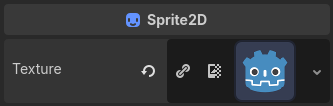
TEXTURE is a built-in variable that references the base texture of a node. In this example, it's the Godot icon that I have assigned to the Sprite2DSprite2D node's Texture property.
The Godot icon used as the Sprite2D texture
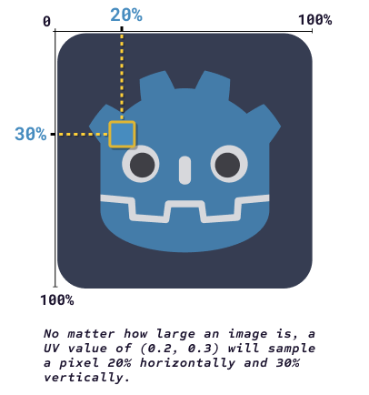
When you pass the UV coordinates as the second parameter, for each pixel the GPU has to render, the shader samples the texel (short for "texture pixel") corresponding to that position. The texture() function returns that color as a vec4 which can be directly assigned to the COLOR built-in.
For example, a UV coordinate of (0.2, 0.3) will sample a texel color 20% across and 30% down the texture. This process is repeated for every pixel of the sprite.
What if UV coordinates don't exactly correspond to texture coordinates?
A texture has a fixed number of texels, each equal in size. For example, when we say that a texture is 32 by 32 pixels, it means it has 32 rows of 32 pixels each.
What happens when you try sampling the color at the UV coordinates (0.1, 0.1) on a texture that's 32 by 32 pixels?
Since UV coordinates represent percentages, 0.1 in this context means 10% of 32. That's 3.2! But there's a fixed number of texels: there is one at the coordinates (2, 2) and another at (3, 3), but there is no texel at (3.2, 3.2).
To handle this, Godot needs to approximate a color that would fit at that coordinate. This decision is based on the texture's filter mode. The two most common ones are nearest and linear (you might have seen them in drawing applications).
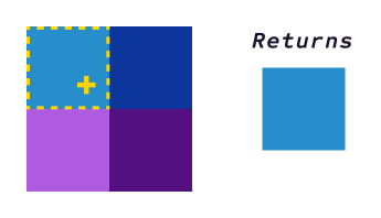
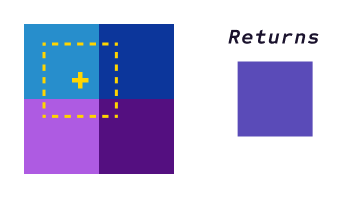
Nearest returns the closest texel to the UV coordinate, disregarding other neighboring texels. In this diagram, the yellow cross represents the current UV coordinate, and the dashed line represents the closest texel.
With the nearest filter, the function returns the closest texel
Linear returns a color mix of the texels surrounding the UV coordinate:
With the linear filter, the function returns the weighted average of neighboring texels
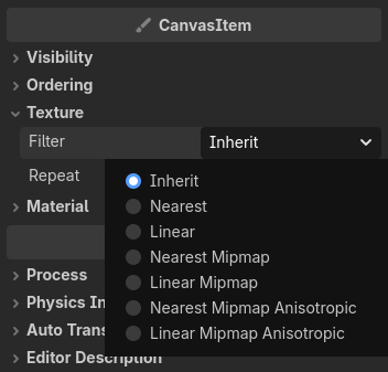
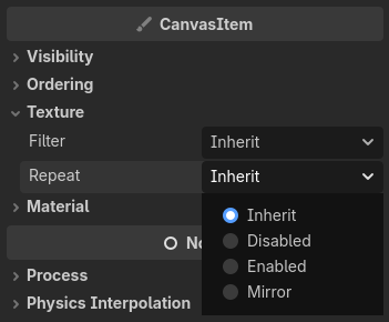
You can change the texture's filter mode on 2D nodes in the Inspector. Look for the TextureFilter property.
The texture's filter mode property
Take a moment to think about how this differs from the sine wave we used earlier.
Every single pixel was described mathematically by the same formula:
sin(TIME + UV.x *20.0);
Change the formula and the entire effect changes according to it.
A texture works differently. Instead of calculating a value, the shader looks up a value that has already been stored in the texture. This gives you a lot more freedom:
Values can be completely arbitrary. They don't have to follow a mathematical pattern.
You can edit your image in a drawing program to change the effect across the entire texture or by editing only one portion of the texture.
If textures are so useful, why don't we use them all the time?
Textures have their limitations:
They have finite resolution. A texture can only store a fixed number of pixels, so an effect using textures might lose fidelity if the texture is too small.
They take up memory. Textures need to be stored in the graphics card's memory. The larger the texture, the more memory it uses.
They are less flexible. With procedural effects, you can use uniforms to change the final effect even while the game is running. With textures, you often need to open them in an image editing program and edit them manually instead.
In practice, we use both textures and procedural generation techniques together frequently in shaders. They each have their strengths and weaknesses. Use them together to get the best of both worlds!
16. Deforming the portal with a noise texture
Natural phenomena have some randomness to them. Be it grass blades scattered in a field, cloud shapes, or even the colors of your eyes, irregularities are always there.
Randomness in grassRandomness in cloudsRandomness in an eye
To make the portal's movement look natural, we need an irregular texture.
So far, TEXTURE has referred to the Godot icon assigned to our Sprite2DSprite2D. Without a texture, Sprite2DSprite2D nodes don't have any size, so we used the icon to have an area on which to draw the effect. However, we're not using the icon for any other purpose, so let's replace it with a procedurally generated texture that has a cloud-like look: a noise texture.
Creating the noise texture
With your Sprite2DSprite2D node selected, in the Inspector, click the LoopReset icon next to the Texture property to remove the Godot icon texture.
Then, click on the empty slot next to the Texture property and select NoiseTexture2DNoiseTexture2D to replace it with a new empty noise texture.
Changing the texture to NoiseTexture2D
Click the newly created NoiseTexture2DNoiseTexture2D to expand its properties. Click the empty slot next to the Noise property and select FastNoiseLiteFastNoiseLite.
These steps create an empty texture and give it an algorithm that can generate a chaotic texture, called a noise texture, in that empty image:
Creating FastNoiseLite
Click FastNoiseLiteFastNoiseLite to reveal its properties and a preview of the noise texture. Set the following properties:
Noise: Verify that it is set to Simplex Smooth. It's one of the procedural generation algorithms offered by Godot.
Frequency: Lower it to 0.005. This controls the density of the effect.
SimplexNoise Properties
Feel free to play around with the properties to get a sense of how each affects the final noise texture!
OldDew
Teacher at GDQuest
Currently, we don't use this noise texture in our code, but if you were to replace the fragment function with the following code, this would result in the noise texture being sampled instead of the Godot icon:
voidfragment(){
COLOR =texture(TEXTURE, UV);}
We are not limited to displaying images, though. Sampling a texture returns a color value, which is a series of numbers representing the red, green, and blue channels of the color. We can use those values to calculate how much we want to displace the pixel's original distance from the center to deform the portal shape.
Using the noise texture to deform the portal
The noise texture is grayscale. Since shades of gray appear when there are equal amounts of red, green and blue values, we can use any channel to get a value between 0.0 and 1.0.
Let's replace the oscillation with a noise sample and add that value to the distance calculation. Update your code to sample from the noise texture like this:
Since the noise values range between 0.0 and 1.0, the displacement is too strong, which causes the shape to largely disappear. Let's add a uniform to scale down the displacement:
That's much better! But why does the noise deform the portal in this way, with jagged edges?
That's because every pixel samples a different shade of gray from the noise texture. The shader adds that value to the pixel's measured distance from the portal's center:
A brighter noise value adds a larger number to the calculated distance, making the pixel reach the portal's edge sooner. This pulls it closer to the center.
A darker noise value adds a smaller number, so those regions remain closer to the original outline.
Different noise values affecting the final shape in their own way
This is how you create deformation in a fragment shader. You add and subtract values from a distance or from the UV built-in to offset pixels.
With this change, we lost the portal's animation. We have a more chaotic deformation, but it's completely static. Let's reintroduce movement by panning the texture over time.
OldDew
Teacher at GDQuest
Offsetting UVs to pan the texture
You can modify the coordinates from which you sample a texture to pan, scale, or even rotate the texture. For example, adding 0.5 to UV.x when sampling the noise texture moves the texture to the left:
voidfragment(){vec2 sample_uv =vec2(UV.x +0.5, UV.y);
COLOR =texture(TEXTURE, sample_uv);}
This might look weird at first, but it's actually what you expect to see when you sample outside the 0.0 to 1.0 range. When you add 0.5 to UV.x, you shift the sample coordinates, so points that used to read the right half of the texture now fall beyond its edge.
For example, a pixel at UV coordinates vec2(0.0, 0.0) now samples the texture at vec2(0.5, 0.0). One at vec2(1.0, 0.0) samples it at vec2(1.5, 0.0).
Why does the texture move left when we add?
Adding to the UV coordinates moves the sampling points and not the texture itself.
After adding 0.5, the pixel at UV.x == 0.0 reads the texture from 0.5. That means the texture content originally found halfway across is now displayed at the left edge.
Reading this text explanation alone may not be very intuitive, though. To better understand shaders, you sometimes need to zoom out of what the code does to a pixel and watch how it changes the shader as a whole.
It's not a perfect analogy, but you can think of the UV coordinates as a shader's canvas or as a camera. Inside an image editing program, when you move the canvas or camera to the right, you shift the view to the right. Relative to the canvas, the image shifts left.
This short clip illustrates what happens when shifting the UV coordinates to the right. The square area that's moving shows what the UVs sample:
Moving the Canvas of the noise image
But 1.5 lies outside the texture's usual 0.0 to 1.0 UV coordinate range. So what happens when you try to sample it? By default, it stretches the last pixel of the texture and produces these strange lines. But we can change that through the texture's repeat mode.
Repeat Modes
Texture repeat modes define what happens when sampling a texture outside of the 0.0 to 1.0 interval. There are three repeat modes supported in Godot:
Disabled: This is the default mode, and when it's set, the texture does not repeat. When you sample outside the 0.0 to 1.0 interval, the coordinate gets clamped to the 0.0 to 1.0 range. In the previous example, sampling at vec2(1.5, 0.0) actually samples the texture at vec2(1.0, 0.0). The same happens for every horizontal coordinate between 1.0 and 1.5, so they all sample from the texture's right edge. This is what creates the straight horizontal lines.
Enabled: The texture repeats. The sampling point wraps around the 0.0 to 1.0 range as if the texture were tiled infinitely in all directions. For example, when the UV coordinates are vec2(1.5, 0.0), the texture is sampled at vec2(0.5, 0.0).
Mirror: The texture repeats, but every other tile is flipped.
You can change the texture repeat mode of any 2D node in the Inspector under TextureRepeat.
The texture's repeat mode property
Here's the previous shader when the noise texture is sampled with different repeat modes:
Repeat Mode: Disabled
Repeat Mode: Enabled
Repeat Mode: Mirror
We want the portal to animate continuously, so set the TextureRepeat property to Enabled. This allows us to use TIME to animate the texture sampling position and pan the texture. This example shows how to pan the texture using TIME:
voidfragment(){vec2 sample_uv =vec2(UV.x + TIME, UV.y);
COLOR =texture(TEXTURE, sample_uv);}
The illusion of a repeating, natural pattern is broken by the hard seam that appears where the texture repeats. We can fix that by making our noise texture seamless.
In the Inspector, turn on the TextureSeamless property. This makes the noise texture repeat seamlessly by blending the edges of the texture.
In some cases, the seam might still be visible after turning on the Seamless property. You can fix that by adjusting the blend distance with the Seamless Blend Skirt property:
Making the noise texture seamless
The pattern becomes harder to notice:
voidfragment(){vec2 sample_uv =vec2(UV.x + TIME, UV.y);
COLOR =texture(TEXTURE, sample_uv);}
To give the noise more variety, we can change both the horizontal and vertical components of the sampling coordinates to make the noise move diagonally:
voidfragment(){vec2 sample_uv =vec2(UV.x + TIME, UV.y + TIME);
COLOR =texture(TEXTURE, sample_uv);}
Or even better, we can control the direction of the noise with a uniform vector:
Noise Direction
uniformvec2 noise_direction =vec2(1.0,1.0);voidfragment(){vec2 sample_uv = UV + TIME * noise_direction;
COLOR =texture(TEXTURE, sample_uv);}
Why can we add the time to the UV directly in this case?
In the code listing above, we are multiplying the TIME built-in by the noise_direction vector. When you multiply a single number by a vec2 value, the computer multiplies each component of the vec2 by the number and returns a new vec2 value.
We can directly add the result of the multiplication to the UV built-in because it is also a vec2 value.
That's why, instead of writing this:
vec2 sample_uv =vec2(
UV.x + TIME * noise_direction.x,
UV.y + TIME * noise_direction.y
);
We can simplify this into:
vec2 sample_uv = UV + TIME * noise_direction;
I find that on top of shortening the line, it makes it easier to understand: we are adding a direction value to the UV coordinates.
To scale the texture panning speed, we can add a new uniform that multiplies the direction and scales the speed. You could also change the x and y components of the noise direction vector instead, but using a single number to scale the speed is easier:
Noise Direction
Noise Speed
uniformvec2 noise_direction =vec2(1.0,1.0);uniformfloat noise_speed :hint_range(0.0,1.0)=0.1;voidfragment(){vec2 sample_uv = UV + TIME * noise_direction * noise_speed;
COLOR =texture(TEXTURE, sample_uv);}
Let's apply this panning noise texture to the portal shader to see how it deforms the shape over time.
Update the portal shader code: add the noise_direction and noise_speed uniforms, calculate sample_uv, and use it instead of UV when sampling the noise texture:
When I change the noise direction or speed, the picture jumps. Why is that?
We animate the shader using the TIME value, which is the time since the engine started. This number is constantly going up.
So long as we keep the animation parameters fixed (like noise_speed), the fact that time is going up gives us a continuous animation. But when we change uniforms like noise_speed, suddenly we have the same large TIME value, but we multiply it by a different number, which produces a completely different result.
For example, if TIME is 10 and noise_speed is 1.0, then TIME * noise_speed is 10. But if you change noise_speed to 0.2, then TIME * noise_speed is suddenly equal to 2.
There is a jump in the result of our multiplication, and this change propagates to the rest of our shader, which is why the image also jumps.
With the noise distortion in place, add the breathing oscillation back to the distance calculation to make the effect more convincing. I split the distance_from_center calculation over multiple lines to make it easier for you to read on this website.
There are still plenty of ways to push the effect further, but the effect now has a solid foundation. What started as a flat color is now a configurable, animated portal.
You learned how to:
Write a program that runs in parallel for all pixels.
Use built-ins like COLOR, UV, TIME, and TEXTURE.
Represent colors, positions and directions with vectors.
Understand and debug shader code by visualizing intermediate values.
Use built-in functions like step() and smoothstep() to create and soften masks.
Combine masks to create complex shapes.
Expose meaningful controls with uniforms and uniform hints.
Animate values with time and oscillating functions like sin().
Reshape an effect by changing its mathematical inputs.
Sample textures and animate them.
Use filtering and repeat modes to gain better control over how you sample textures.
Combine predictable procedural motion (the oscillation) with noise to create natural-looking variation.
And perhaps most importantly, you practiced one of the most useful shader development habits: working iteratively.
You broke down complicated problems into small ones that you solved one step at a time. You investigated by visualizing each output and experimented every time something wasn't clear.
This process is more important than memorizing any individual function, and you should keep practicing it as you start working on your own shaders.
OldDew
Teacher at GDQuest
Until now, we've worked on our shader in isolation. It's time to start using it in the game world by controlling the shader's uniforms from a script. Let's learn how to make the portal open when a character or object gets close!
Yes, you can use multiple textures in a shader by using sampler2D uniforms. It's very common to need multiple textures in a shader, actually, so you will often use these.
A sampler2D exposes a shader parameter, which allows you to pick any kind of texture.
uniformsampler2D my_texture;
Sampler2D shader parameter using a noise texture
You can then sample it with the texture() function similarly to how you did with the TEXTURE built-in:
uniformsampler2D my_texture;voidfragment(){
COLOR =texture(my_texture, UV);}
Since this isn't the node's main texture, the sampling and repeat modes are out of its control.
Instead, you specify these properties through hints. For instance, this code snippet exposes a texture with the nearest filter mode and enabled repeat mode.
In this section, we will learn how to control the shader uniforms we defined in the shader code from a game script. This allows you to make the shader interactive in the game.
For that, we will set up a player-controlled ship, and we will give our portal an area to detect when the ship gets close to it.
In this section, I'm assuming that you are comfortable creating nodes and will go relatively quickly through the basic scene setup to focus our attention on the shader-related scripts.
OldDew
Teacher at GDQuest
Let's start by creating our spaceship. Create a new scene with a Node2DNode2D as the root (it will represent our "level"), then add a CharacterBody2DCharacterBody2D as a child of the Node2DNode2D for controlling the player ship.
Add a Sprite2DSprite2D as a child of the CharacterBody2DCharacterBody2D node and give it a texture to make the player ship visible. You can use this sprite from Learn 2D Gamedev from Zero with Godot 4:
Right-click the image and save the sprite to your project
Then add a CollisionShape2DCollisionShape2D as a child of the CharacterBody2DCharacterBody2D node and assign a CircleShape2DCircleShape2D to its CollisionShape2DShape property. Make the circle roughly match the size of the sprite.
Be careful to make the CollisionShape2DCollisionShape2D node a direct child of the CharacterBody2DCharacterBody2D node, and not a child of the Sprite2DSprite2D node.
All that's left for the player is to give it the ability to move. Attach a new script called player.gd to the CharacterBody2DCharacterBody2D node and copy this code snippet inside of it:
It rotates the ship when the player presses the left and right keys.
It moves forward or backward (in the direction the ship is facing) when the player presses the up and down keys.
Time to test that your ship is working as intended! Select the CharacterBody2DCharacterBody2D node and place it vertically centered near the left edge of the game view bounds.
We want to give it a child sprite and collision shape just like the ship. But the sprite should be the portal that we created in this guide.
You can navigate back to the scene where we designed the portal and copy and paste the Sprite2DSprite2D node as a child of the Area2DArea2D node. Reset its TransformPosition to Vector2(0, 0).
The distortion is not working anymore on my portal
Whether you recreated the effect from scratch or you copied it, if the distortion is not working, verify that:
The portal sprite has a noise texture attached and configured in its Texture property.
The sprite's repeat mode, found in the Inspector under TextureRepeat, is set to Enabled.
The Displacement Strength shader parameter is set to a value greater than 0.0.
You might find that the portal Sprite2DSprite2D is too large. That's because its size depends on the size of the noise texture. Scale the sprite down to better fit the scene.
Lastly, add a CollisionShape2DCollisionShape2D node as a child of the Area2DArea2D node. Give it a large CircleShape2DCircleShape2D shape to define the portal's detection area. When the player enters the area, the portal will open.
Under the CollisionShape2DShape property, select the circle shape, but this time, make it larger than the portal, so the opening animation can finish before the player reaches it.
Creating the portal activation area
Opening the portal when the ship is near
Before moving on, let's think about how the portal should behave. We want to make it react to the player's distance. When the ship is far away, the portal is just a closed, small distortion in space.
When the ship gets close to the portal, the portal opens and stabilizes as a welcoming sign to the player. On the other hand, if the ship leaves the area, then the portal should return to its initial closed state.
Closed portal state
Open portal state
With this in mind, let's change the shader parameters so the portal starts closed. Select the portal's Sprite2DSprite2D node and expand MaterialMaterialShader Parameters. Then, change these shader parameters so that the portal is initially closed:
Radius: 0.15
Breathing Strength: 0.0
Displacement Strength: 0.15
The first two parameters reduce the size and tone down the animation, while increasing the displacement strength makes the portal look more erratic.
Now, attach a new script called portal.gd to the Area2DArea2D node.
Area2DArea2D nodes emit body_entered and body_exited signals when a physics body like a CharacterBody2DCharacterBody2D node enters or leaves their region. Connect both signals to two new functions in your script, _on_body_entered() and _on_body_exited():
Let's create an _animate_portal() function that takes in the shader parameter values we'll animate to. Add the function declaration to your script, with parameters for the three shader uniforms we want to animate:
To control a shader's properties, we first need to get a reference to the shader material, a value of type ShaderMaterialShaderMaterial. In this case, it's the material attached to the Sprite2DSprite2D child of the portal.
Each ShaderMaterialShaderMaterial exposes two functions that allow you to get and set shader uniforms: get_shader_parameter() and set_shader_parameter(). These functions are all we need to pass values between our game logic and the shader.
In this case, set_shader_parameter() can be used to tell a material to set any shader parameter to a new value. You need to call it with two parameters:
The exact name of the uniform variable you want to change as a StringNameStringName.
The new value the uniform should take.
Let's use this in the _animate_portal() function. Update the function to set the three shader uniforms:
We can call _animate_portal() in the _on_body_entered() and _on_body_exited() functions to open and close the portal. Update the functions to call _animate_portal() with appropriate arguments. I've picked these values by testing the game with different settings and tweaking them until they looked right:
If you run the scene and move the ship into the portal's area, at this point, the portal should grow and shrink instantly as the ship enters and exits its area:
Portal growing and shrinking instantly as the ship enters its area
If I create multiple portals, they all open and close at the same time. How can I fix that?
A material is a resource in Godot. By default, a resource is shared across every entity that uses it for performance: multiple nodes can use the same material, script, or texture without duplicating it or loading it multiple times.
Changing the properties of a resource shared by multiple nodes leads to it being updated for every single node. If you create multiple copies of your portal area, you will get something like this:
All portals open despite the player intersecting only one area
A common way to avoid this is to duplicate the resource for each instance that needs a unique copy. But for shaders, we don't have to do that. Godot has a special feature that makes shader parameters instance-specific while maximizing rendering performance: instance uniforms.
If you want to change a uniform for a single portal, you need to define it as an instance uniform. This creates an instance shader parameter that's editable in the Inspector and is bound to the CanvasItemCanvasItem holding the ShaderMaterialShaderMaterial. For example, you can make the radius an instance uniform by adding the instance keyword before the uniform declaration:
In the editor, the instance uniform parameter appears under the MaterialInstance Shader Parameters category, outside of the ShaderMaterialShaderMaterial resource, to make it clear that it's an instance-specific parameter and not a shared shader parameter anymore.
Radius as an instance shader parameter
To modify an instance uniform from a script, instead of calling the ShaderMaterialShaderMaterial's set_shader_parameter() function, you call the set_instance_shader_parameter() function on the node itself (unlike set_shader_parameter(), this function is part of 2D nodes, not the ShaderMaterialShaderMaterial).
To make the portals behave correctly, make the breathing_strength and displacement_strength instance uniforms as well. Then change the _animate_portal() function to set the instance parameters. In that case, we don't reference the ShaderMaterialShaderMaterial anymore:
Portals correctly opening as the ship enters their area
Animating the opening and closing
The portal changes state, but it still snaps instantly instead of transitioning smoothly. We'll animate it with a tween.
We can use Tween.tween_method() to call a function every frame with an interpolated value for the duration of an animation.
Note that Tween.tween_method() only forwards one value to the function it calls, but set_shader_parameter() needs two arguments: the parameter's name and its value.
We can work around this by wrapping the call in a lambda function that binds (saves) the shader uniform name. For example, this is what animating the radius looks like with this approach:
var tween :=create_tween()
tween.tween_method(funcupdate_radius(value):
_material.set_shader_parameter("radius", value),
_material.get_shader_parameter("radius"),
radius,0.5,)
This code animates the radius from the current value to the new one over 0.5 seconds. It calls the lambda function update_radius() for every value between the initial radius and the new one.
You can repeat this for every other parameter, and you get:
This works, but it's a bit verbose. Not only that, but you also need to know the starting value of each parameter.
Here's a trick you can use to shorten this code.
You can avoid calling set_shader_parameter() by directly modifying the shader property. You can do that with the tween_property() function. It takes four arguments:
The object holding the property to animate
The property to animate, as a string
The target value to reach at the end of the animation
The duration of the animation
This example shows how to use tween_property() to animate the radius property of a ShaderMaterialShaderMaterial:
The important difference to notice is the way we refer to the radius property.
Before, we used the uniform name "radius" and the set_shader_parameter() function identified the uniform for us.
This time we take that job into our own hands. Since radius is not a direct property of the material, but rather a shader parameter, we refer to it by its property path: "shader_parameter/radius". In Godot, just like you can access nodes by path, you can also read and set many node properties by path like this.
Applying this change to all properties makes the function easier to read. You can now go ahead and update your animate portal function like this:
We're almost there! There are just a few issues to resolve.
First, by default, tween animations start one after the other, so the radius animation finishes before breathing starts, and breathing finishes before displacement starts.
Instead, they should start all at once. You can fix that by making the tween parallel upon creating it:
Then, if the ship quickly enters and exits the portal's activation area, multiple tween instances from different _animate_portal() function calls will fight over animating the properties, leading to visual artifacts.
For this animation, it'd be best to have one tween so you can either wait or interrupt it before you start a new one.
A property of tweens is that, after they finish their job, their lifecycle ends.
This means we can define the tween at the top of the script, and inside the function, check if the tween still exists, or more concretely, if there's an unfinished animation. If that's the case, we call tween.kill() to finish the animation early and move on with creating the new one.
Update the _animate_portal() function to check if the tween still exists before creating a new one. Let's also add a transition to improve the animation feel:
You can now add details to the scene to get a better sense of how the effect fits into the game world. Hide the debug collision shapes, add a background, and adjust the tween easing or even the portal itself.
Portal growing and shrinking smoothly as the ship enters its region
Congratulations on reaching this point! On top of learning many shader techniques, you now know how to make your shader interact with the game world.
By now, you should be familiar with enough basic shader techniques to start experimenting on your own.
If you haven't memorized anything yet, don't worry. It's normal. Look at all the sections in this guide again and use it as a reference! It takes a lot of practice and repetition for things to stick in your memory.
If you want to learn more, the bonus section below will teach you how to create procedural gradients to take the portal a step further.
OldDew
Teacher at GDQuest
Code Reference: res://portal.gd
This is the complete code of the portal script, which animates the portal opening and closing:
We have a functional portal with flat colors that can work with a compatible art style. But if your game has a more painterly art style, you need color variation. Gradients are a great way to make the portal fit in with the art styles of different indie games.
But how can you create a gradient? To do that, we have to go back to when we created the portal's circular mask.
We used the distance of a pixel from the center to determine if the pixel was inside or outside of the mask. When we output the distance as color, we saw a grayscale gradient that came from the center:
voidfragment(){vec2 center =vec2(0.5,0.5);float distance_from_center =distance(UV, center);
COLOR =vec4(vec3(distance_from_center),1.0);}
You can create colored gradients starting from this grayscale mask. To turn this image into a colored gradient, we need to pick two colors and blend them based on the calculated distance.
GDShader allows us to blend two colors with the mix() built-in function. It takes three inputs:
The first color
The second color
A blending factor ranging from 0.0 to 1.0
In reality, the mix function is not limited to colors. The first two arguments can be anything ranging from floats to vec4 variables. We will blend between two vec3 values, each representing a color.
The blending factor (the third argument) is what determines the final result:
When it's 0.0, the result is the first color
When it's 1.0, the result is the second color
When it's 0.5, the result is a perfect blend between the two
When it's 0.2, the result is mostly the starting value, with a little of the end value mixed in
Why do we use a vec3 for our gradient colors instead of vec4?
Remember: Determining the shader's transparency is the role of the outer mask.
COLOR =vec4(gradient, mask_outer);
This leaves three channels for the final_color: red, green and blue. Together, they fit into a vec3.
Let's define two new uniforms and use the distance from the center as a blending factor. If you'd like to follow along, you can write this code in a new shader. This will let you experiment with radial gradients.
Black
Blue
uniformvec3 black: source_color =vec3(0.0,0.0,0.0);uniformvec3 blue: source_color =vec3(0.02,0.04,0.51);voidfragment(){vec2 center =vec2(0.5,0.5);float distance_from_center =distance(UV, center);vec3 gradient =mix( black, blue, distance_from_center
); COLOR =vec4(gradient,1.0);}
This shader creates a gradient that transitions from black to dark blue. As the distance from the center increases, the blending factor increases as well, which produces a smooth transition between the two colors.
But the colors we're seeing in the result are not exactly the colors picked as inputs in the code. The blue color is darker than expected:
The expected shade of blue
The brightest blue shade in our shader
On the left, you have the blue color as written in the code, and on the right side, you have the exact shade I picked using a color picker on the rendered shader.
The blue on the right is darker because of how the blending factor is calculated.
Every pixel checks how close it is to the point in the middle. Because of this, the distance will never reach 1.0. This means that the mix() function doesn't actually return the end color. Some of the start color is always mixed in.
Fortunately, we have already used a function that maps a value between 0.0 and 1.0: smoothstep(). Instead of using the raw distance as the blending factor, we can use smoothstep() to remap it to the range expected by the mix() function.
Let's define two new uniforms and use them to remap the gradient:
inner_gradient_start: the distance from the center at which the gradient starts. Up to that distance, only the starting color will be present.
inner_gradient_width: how long the gradient should span before it reaches the end color.
Let's go outward along the distance starting from the center to analyze what happens.
Initially, the distance is smaller than the default inner_gradient_start value of 0.1. In this case, smoothstep() clamps the gradient factor to 0.0. A mix() function with a factor of 0.0 always returns the starting value. In our case, it's the black color.
As the distance grows past 0.1, the smoothstep() function returns a value between 0.0 and 1.0. Using this value as a factor of mix() returns a blend between its starting and ending values.
Once the distance is greater than inner_gradient_start + inner_gradient_width, smoothstep() returns 1.0. This weight causes mix() to return the blue color.
This is how the code gives you a configurable gradient.
Masking the gradient
Now that we know how to create a gradient, one question remains: How do we apply it to the inner shape of the portal? Previously, we applied each color to its corresponding shape by multiplying the color by its mask:
It works exactly the same way for our gradient! The gradient gives each pixel a different color, and multiplying that color by the mask shows or hides pixels from the gradient.
We can even do better than that. The mask itself does not control the gradient's pattern or deform it. If we use distance(UV, center), our gradient is perfectly circular. Instead of that, we can use the portal's displaced distance_from_center. This is the value to which we apply the noise displacement and our oscillation animation. It will give our gradient a cloudy texture, like this (I accentuated the contrast in this example):
Back in the portal shader, replace the color_inner uniform with two gradient colors named inner_start_color and inner_end_color. Add the two uniforms to control the gradient, then calculate inner_gradient from distance_from_center:
The inner mask defines the region in which the gradient gets drawn, keeping the original shape of the portal. Since we only changed the coloring process, the rest of the shader roughly stays the same.
The gradient also inherits the portal's movement. Unlike our standalone experiment, where the distance calculation was isolated to help us focus on the gradient implementation, the portal's distance_from_center includes the noise displacement and breathing oscillation.
Reusing our distance_from_center to generate the gradient makes the gradient inherit all the same properties as the portal's silhouette.
All that's left now is to apply the same technique to the rim:
Replace the color_rim uniform with two new uniforms representing the rim's gradient colors: rim_start_color and rim_end_color.
Define a uniform for the rim gradient width: rim_gradient_width.
Then, as the rim will usually be thin, leave the gradient starting point at the rim's inner radius. You don't need a new uniform for that. The starting point will be radius - rim_width.
Finally, multiply the mask_rim value by the newly calculated gradient color, which wel wil store in a vec3 called rim_gradient.
With the rim using the same gradient technique, the portal shader is now complete.
Here is the final shader with everything put together:
Radius
Rim Width
Softness
Inner Gradient Start
Inner Gradient Width
Inner Start Color
Inner End Color
Rim Start Color
Rim End Color
Rim Gradient Width
Breathing Strength
Displacement Strength
Noise Direction
Noise Speed
Play with the different parameters and colors to adapt the shader to your game. This is the result I got using dark brown, orange, and yellow tones and a low softness: